正在加载图片...

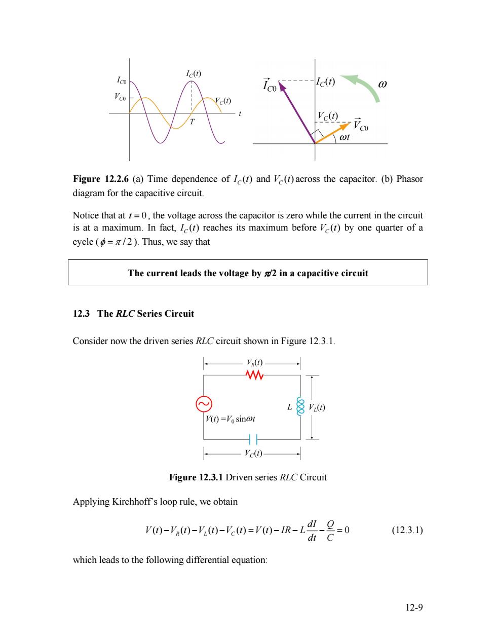
Ic(t) Ic(t) 0 Ve(t) ¥C0 wt Figure 12.2.6 (a)Time dependence of I(t)and V(t)across the capacitor.(b)Phasor diagram for the capacitive circuit. Notice that at t=0,the voltage across the capacitor is zero while the current in the circuit is at a maximum.In fact,I(t)reaches its maximum before V(t)by one quarter of a cycle (=/2).Thus,we say that The current leads the voltage by 2 in a capacitive circuit 12.3 The RLC Series Circuit Consider now the driven series RLC circuit shown in Figure 12.3.1. VR(t) W V(t)=Vosin@t Ve(t) Figure 12.3.1 Driven series RLC Circuit Applying Kirchhoffs loop rule,we obtain V)-'0)-y(0-0=r0-1R-L"-2=0 (12.3.1) dt C which leads to the following differential equation: 12-9Figure 12.2.6 (a) Time dependence of ( ) CI t and across the capacitor. (b) Phasor diagram for the capacitive circuit. ( ) VC t Notice that at , the voltage across the capacitor is zero while the current in the circuit is at a maximum. In fact, t = 0 ( ) CI t reaches its maximum before by one quarter of a cycle ( ( ) VC t φ = π / 2 ). Thus, we say that The current leads the voltage by π/2 in a capacitive circuit 12.3 The RLC Series Circuit Consider now the driven series RLC circuit shown in Figure 12.3.1. Figure 12.3.1 Driven series RLC Circuit Applying Kirchhoff’s loop rule, we obtain ( ) ( ) ( ) ( ) ( ) 0 R L C dI Q V t V t V t V t V t IR L dt C − − − = − − − = (12.3.1) which leads to the following differential equation: 12-9