正在加载图片...
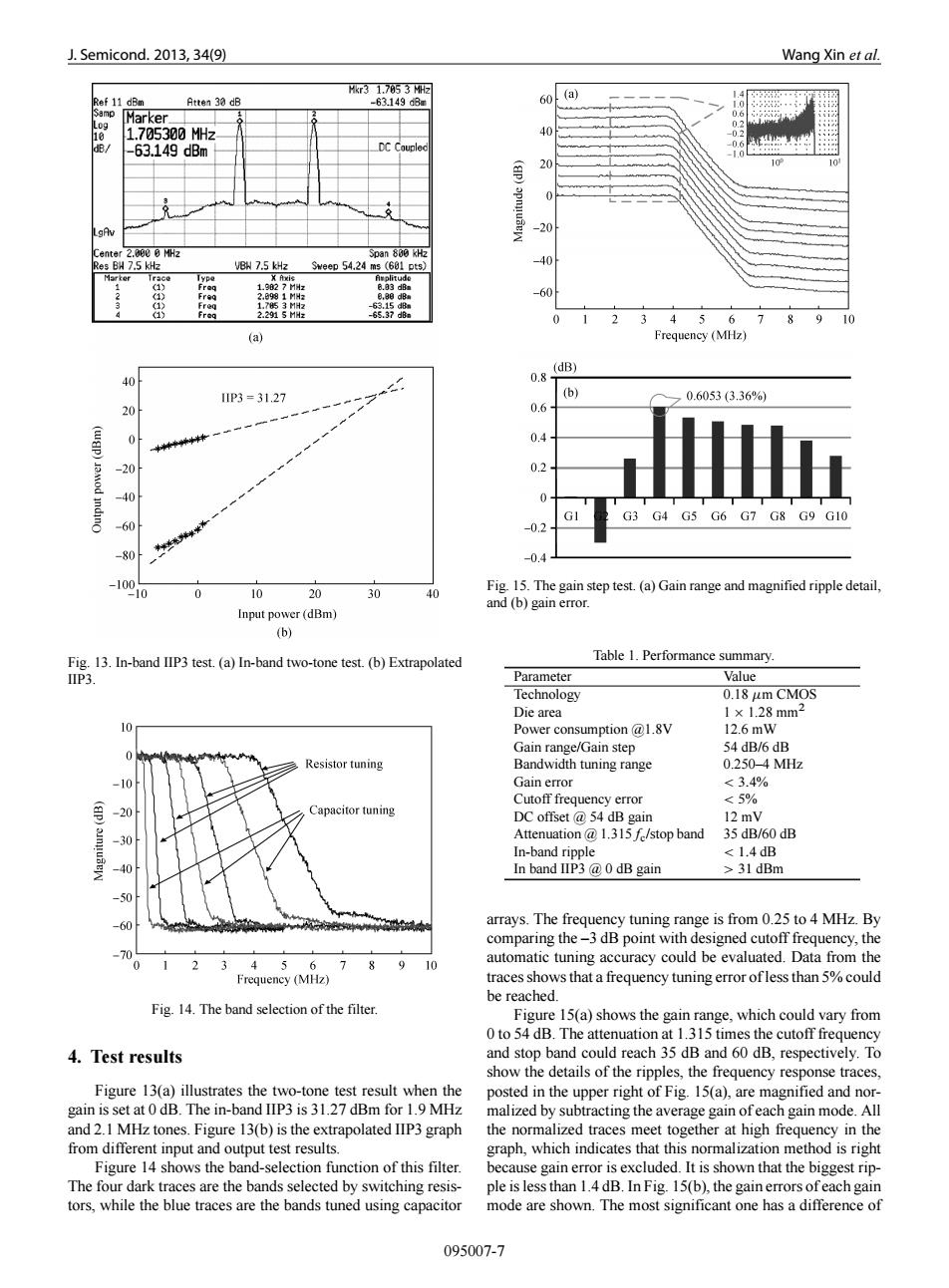
J.Semicond.2013,34(9) Wang Xin et al. Hkr31.7853M2 Ref 11 dBm Atten 30 dB 60 (a) -63149a3m amp Marker☐ 0.d 1.705300MHz 40 dB/ -63.149dBm DC Couple 20 .gAv -20 Center 2.000 0 MHz 500n800H2 Res BH 7.5 kHz VBW 7.5 kHz Sweep 54.24 ms (601 pts) -40 28981MH 8.30d8 -60 3 45678910 (a) Frequency(MHz) (dB) 40 0.8 IIP3=31.27 (b) 0.6053(3.36%) 20 0.6 0.4 30 0.2 40 0 GI G3 G4 G5 G6 G7 G8 G9 G10 -60 米丝米米 -0.2 -80 -0.4 -100 10 10 20 30 Fig.15.The gain step test.(a)Gain range and magnified ripple detail, 40 and (b)gain error Input power(dBm) (b) Fig.13.In-band IIP3 test.(a)In-band two-tone test.(b)Extrapolated Table 1.Performance summary IIP3. Parameter Value Technology 0.18 um CMOS Die area 1×1.28mm2 10 Power consumption @1.8V 12.6mW 54 dB/6 dB 0 Gain range/Gain step Resistor tuning Bandwidth tuning range 0.250-4MHz 10 Gain error <3.4% Cutoff frequency error <5% Capacitor tuning DC offset 54 dB gain 12 mV -30 Attenuation @1.315 f/stop band 35 dB/60 dB In-band ripple <1.4dB In band IIP3 @0 dB gain >31 dBm -60 arrays.The frequency tuning range is from 0.25 to 4 MHz.By comparing the-3 dB point with designed cutoff frequency,the -70 3 3 4 56789 10 automatic tuning accuracy could be evaluated.Data from the Frequency (MHz) traces shows that a frequency tuning error ofless than 5%could be reached. Fig.14.The band selection of the filter. Figure 15(a)shows the gain range,which could vary from 0 to 54 dB.The attenuation at 1.315 times the cutoff frequency 4.Test results and stop band could reach 35 dB and 60 dB,respectively.To show the details of the ripples,the frequency response traces, Figure 13(a)illustrates the two-tone test result when the posted in the upper right of Fig.15(a),are magnified and nor- gain is set at 0 dB.The in-band IIP3 is 31.27 dBm for 1.9 MHz malized by subtracting the average gain ofeach gain mode.All and 2.1 MHz tones.Figure 13(b)is the extrapolated IIP3 graph the normalized traces meet together at high frequency in the from different input and output test results. graph,which indicates that this normalization method is right Figure 14 shows the band-selection function of this filter. because gain error is excluded.It is shown that the biggest rip- The four dark traces are the bands selected by switching resis- ple is less than 1.4 dB.In Fig.15(b),the gain errors ofeach gain tors,while the blue traces are the bands tuned using capacitor mode are shown.The most significant one has a difference of 095007-7J. Semicond. 2013, 34(9) Wang Xin et al. Fig. 13. In-band IIP3 test. (a) In-band two-tone test. (b) Extrapolated IIP3. Fig. 14. The band selection of the filter. 4. Test results Figure 13(a) illustrates the two-tone test result when the gain is set at 0 dB. The in-band IIP3 is 31.27 dBm for 1.9 MHz and 2.1 MHz tones. Figure 13(b) is the extrapolated IIP3 graph from different input and output test results. Figure 14 shows the band-selection function of this filter. The four dark traces are the bands selected by switching resistors, while the blue traces are the bands tuned using capacitor Fig. 15. The gain step test. (a) Gain range and magnified ripple detail, and (b) gain error. Table 1. Performance summary. Parameter Value Technology 0.18 m CMOS Die area 1 1.28 mm2 Power consumption @1.8V 12.6 mW Gain range/Gain step 54 dB/6 dB Bandwidth tuning range 0.250–4 MHz Gain error < 3:4% Cutoff frequency error < 5% DC offset @ 54 dB gain 12 mV Attenuation @ 1.315fc/stop band 35 dB/60 dB In-band ripple < 1:4 dB In band IIP3 @ 0 dB gain > 31 dBm arrays. The frequency tuning range is from 0.25 to 4 MHz. By comparing the –3 dB point with designed cutoff frequency, the automatic tuning accuracy could be evaluated. Data from the traces shows that a frequency tuning error of less than 5% could be reached. Figure 15(a) shows the gain range, which could vary from 0 to 54 dB. The attenuation at 1.315 times the cutoff frequency and stop band could reach 35 dB and 60 dB, respectively. To show the details of the ripples, the frequency response traces, posted in the upper right of Fig. 15(a), are magnified and normalized by subtracting the average gain of each gain mode. All the normalized traces meet together at high frequency in the graph, which indicates that this normalization method is right because gain error is excluded. It is shown that the biggest ripple is less than 1.4 dB. In Fig. 15(b), the gain errors of each gain mode are shown. The most significant one has a difference of 095007-7�