正在加载图片...
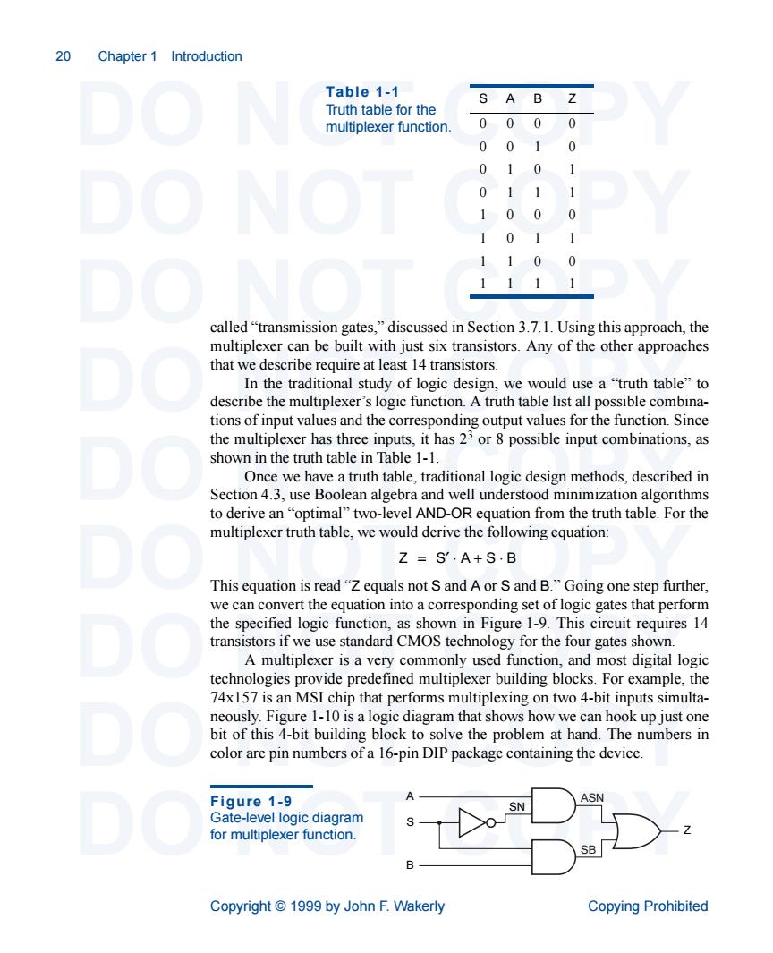
20 Chapter 1 Introduction Table 1-1 Truth table for the S A B Z multiplexer function 0000 0010 0 1 0 0 0 0 0 0 called"transmission gates."discussed in Section 3.7.1.Using this approach,the multiplexer can be built with just six transistors.Any of the other approaches that we describe require at least 14 transistors. In the traditional study of logic design,we would use a"truth table"to describe the multiplexer's logic function.A truth table list all possible combina- tions of input values and the corresponding output values for the function.Since the multiplexer has three inputs,it has 23 or 8 possible input combinations,as shown in the truth table in Table 1-1. Once we have atruth table,traditional log design methods,described in Section 4.3,use Boolean algebra and well understood minimization algorithms to derive an"optimal"two-level AND-OR equation from the truth table.For the multiplexer truth table,we would derive the following equation: Z=S'.A+S.B This equation is read"Z equals not S and A or S and B."Going one step further. transistors if we use standard CMOS technology for the four gates shown. A multiplexer is a very commonly used function,and most digital logic 74x157 is an MSI chip that performs multiplexing on two 4-bit inputs simulta- neously.Figure 1-10 is a logic diagram that shows how we can hook up just one bit of this 4-bit building block to solve the problem at hand.The numbers in color are pin numbers of a 16-pin DIP package containing the device. Figure 1-9 A ASN vel logi C diagram for multiplexer function. Copyright1999 by John F.Wakerly Copying Prohibited 20 Chapter 1 Introduction DO NOT COPY DO NOT COPY DO NOT COPY DO NOT COPY DO NOT COPY DO NOT COPY DO NOT COPY DO NOT COPY DO NOT COPY Copyright © 1999 by John F. Wakerly Copying Prohibited called “transmission gates,” discussed in Section 3.7.1. Using this approach, the multiplexer can be built with just six transistors. Any of the other approaches that we describe require at least 14 transistors. In the traditional study of logic design, we would use a “truth table” to describe the multiplexer’s logic function. A truth table list all possible combinations of input values and the corresponding output values for the function. Since the multiplexer has three inputs, it has 23 or 8 possible input combinations, as shown in the truth table in Table 1-1. Once we have a truth table, traditional logic design methods, described in Section 4.3, use Boolean algebra and well understood minimization algorithms to derive an “optimal” two-level AND-OR equation from the truth table. For the multiplexer truth table, we would derive the following equation: This equation is read “Z equals not S and A or S and B.” Going one step further, we can convert the equation into a corresponding set of logic gates that perform the specified logic function, as shown in Figure 1-9. This circuit requires 14 transistors if we use standard CMOS technology for the four gates shown. A multiplexer is a very commonly used function, and most digital logic technologies provide predefined multiplexer building blocks. For example, the 74x157 is an MSI chip that performs multiplexing on two 4-bit inputs simultaneously. Figure 1-10 is a logic diagram that shows how we can hook up just one bit of this 4-bit building block to solve the problem at hand. The numbers in color are pin numbers of a 16-pin DIP package containing the device. Table 1-1 Truth table for the multiplexer function. SAB Z 000 0 001 0 010 1 011 1 100 0 101 1 110 0 111 1 Z = S′ ⋅ A + S ⋅ B A S B Z SN ASN SB Figure 1-9 Gate-level logic diagram for multiplexer function