正在加载图片...

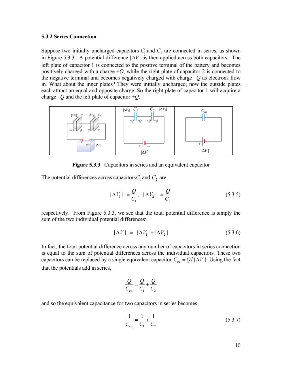
5.3.2 Series Connection Suppose two initially uncharged capacitors C and C,are connected in series,as shown in Figure 5.3.3.A potential difference AV is then applied across both capacitors.The left plate of capacitor 1 is connected to the positive terminal of the battery and becomes positively charged with a charge +0,while the right plate of capacitor 2 is connected to the negative terminal and becomes negatively charged with charge-O as electrons flow in.What about the inner plates?They were initially uncharged;now the outside plates each attract an equal and opposite charge.So the right plate of capacitor 1 will acquire a charge-O and the left plate of capacitor +O AV △M Figure 5.3.3 Capacitors in series and an equivalent capacitor The potential differences across capacitorsC and C,are 1451 1451=g (5.3.5) C2 respectively.From Figure 5.3.3,we see that the total potential difference is simply the sum of the two individual potential differences: |△VI=|△VI+|△VI (5.3.6) In fact,the total potential difference across any number of capacitors in series connection is equal to the sum of potential differences across the individual capacitors.These two capacitors can be replaced by a single equivalent capacitor C/AV.Using the fact that the potentials add in series, =+g Ceg C C2 and so the equivalent capacitance for two capacitors in series becomes 111 (5.3.7) 105.3.2 Series Connection Suppose two initially uncharged capacitors C1 and C2 are connected in series, as shown in Figure 5.3.3. A potential difference | ∆V | is then applied across both capacitors. The left plate of capacitor 1 is connected to the positive terminal of the battery and becomes positively charged with a charge +Q, while the right plate of capacitor 2 is connected to the negative terminal and becomes negatively charged with charge –Q as electrons flow in. What about the inner plates? They were initially uncharged; now the outside plates each attract an equal and opposite charge. So the right plate of capacitor 1 will acquire a charge –Q and the left plate of capacitor +Q. Figure 5.3.3 Capacitors in series and an equivalent capacitor The potential differences across capacitorsC1 and C are 2 1 2 1 2 Q | V | , | V | C C ∆ = ∆ = Q 2 (5.3.5) respectively. From Figure 5.3.3, we see that the total potential difference is simply the sum of the two individual potential differences: 1 | V∆ | = ∆| V ||V + ∆ | (5.3.6) In fact, the total potential difference across any number of capacitors in series connection is equal to the sum of potential differences across the individual capacitors. These two capacitors can be replaced by a single equivalent capacitor eq C Q= / | ∆V |. Using the fact that the potentials add in series, eq 1 2 Q Q Q C C C = + and so the equivalent capacitance for two capacitors in series becomes eq 1 2 1 1 1 C C C = + (5.3.7) 10