正在加载图片...
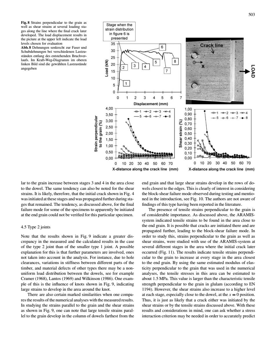
503 Fig.8 Strains pendicular to the Stage when the the fo 35 6 Crack line 30 20 15 7 10 51 0 3 45 400 ent(mm) 00 3.50 3.00 2,50 2,00 0.50 1.50 1.00 0,50 0,00 0.00 0 1020 304050 6070 )20 30 50 60 long the crack line (mm) X-distance along the crack line (mm) lar to the grain increase between stages 3 and 4 in the area close end grain and that large shear strains develop in the rows of do st to the dge This is clearly lyheinitiatc of tens 4.5 Type 2joints 、ble that he9 ing to the Note that the results showr in Fig.9 indicate ter dis propa his str where the initial tem at ever aes the area not taken into account in the analysis.For instance.due to hole cular to the grain to increase at every stage in the area closest rances.varation n suiffness between different parts of the to the end grain.By using the same estimated mod ulus of ela da ber and ma sof oth be a no was used in the Cramer(18).Lantos (19)and Wilkinson (1).One exam about 1.5 MPa.This value is larger than the characteristic tensile ple of this is the innuence of knots show nin Fig.9,indicating perpendicular to the grain in glulam (accor There are also certain marked similarities when one co t each stage especialy close to the dowel.at the position res the results of the numerical nalyses with the n red result Thus.it is just s likely that a crack either w initi I by the strains parallel to ear stra hear stra or by th lel to the grain develop in the column of dowels farthest from the interaction criterion may be needed in order to accurately predict 503 Fig. 8 Strains perpendicular to the grain as well as shear strains at several loading stages along the line where the final crack later developed. The load displacement results in the picture at the upper left indicate the load levels chosen for evaluation Abb. 8 Dehnungen senkrecht zur Faser und Schubdehnungen bei verschiedenen Lastzuständen entlang des entstehenden Bruchverlaufs. Im Kraft-Weg-Diagramm im oberen linken Bild sind die gewählten Lastzustände angegeben lar to the grain increase between stages 3 and 4 in the area close to the dowel. The same tendency can also be noted for the shear strains. It is likely, therefore, that the initial crack shown in Fig. 4 was initiated at these stages and was propagated further during stages that remained. The tendency, as discussed above, for the final failure mode for some of the specimens to apparently be initiated at the end grain could not be verified for this particular specimen. 4.5 Type 2 joints Note that the results shown in Fig. 9 indicate a greater discrepancy in the measured and the calculated results in the case of the type 2 joint than of the smaller type 1 joint. A possible explanation for this is that further parameters are involved, ones not taken into account in the analysis. For instance, due to hole clearances, variations in stiffness between different parts of the timber, and material defects of other types there may be a nonuniform load distribution between the dowels, see for example Cramer (1968), Lantos (1969) and Wilkinson (1986). One example of this is the influence of knots shown in Fig. 9, indicating large strains to develop in the area around the knot. There are also certain marked similarities when one compares the results of the numerical analyses with the measured results. In studying the strains parallel to the grain and the shear strains as shown in Fig. 9, one can note that large tensile strains parallel to the grain develop in the column of dowels farthest from the end grain and that large shear strains develop in the rows of dowels closest to the edges. This is clearly of interest in considering the block-shear failure mode observed during testing and mentioned in the introduction, see Fig. 10. The authors are not aware of findings of this type having been reported in the literature. The presence of tensile strains perpendicular to the grain is of considerable importance. As discussed above, the ARAMISsystem indicated tensile strains to be found in the area close to the end grain. It is possible that cracks are initiated there and are propagated further, leading to the block-shear failure mode. In order to study this, strains perpendicular to the grain as well as shear strains, were studied with use of the ARAMIS-system at several different stages in the area where the initial crack later occurred (Fig. 11). The results indicate tensile strains perpendicular to the grain to increase at every stage in the area closest to the end grain. By using the same estimated modulus of elasticity perpendicular to the grain that was used in the numerical analyses, the tensile stresses in this area can be estimated to about 1.5 MPa. This value is larger than the characteristic tensile strength perpendicular to the grain in glulam (according to EN 1194). However, the shear strains also increase to a higher level at each stage, especially close to the dowel, at the x = 0 position. Thus, it is just as likely that a crack either was initiated by the shear strains or by the tensile strains discussed above. With these results and considerations in mind, one can ask whether a stress interaction criterion may be needed in order to accurately predict