正在加载图片...
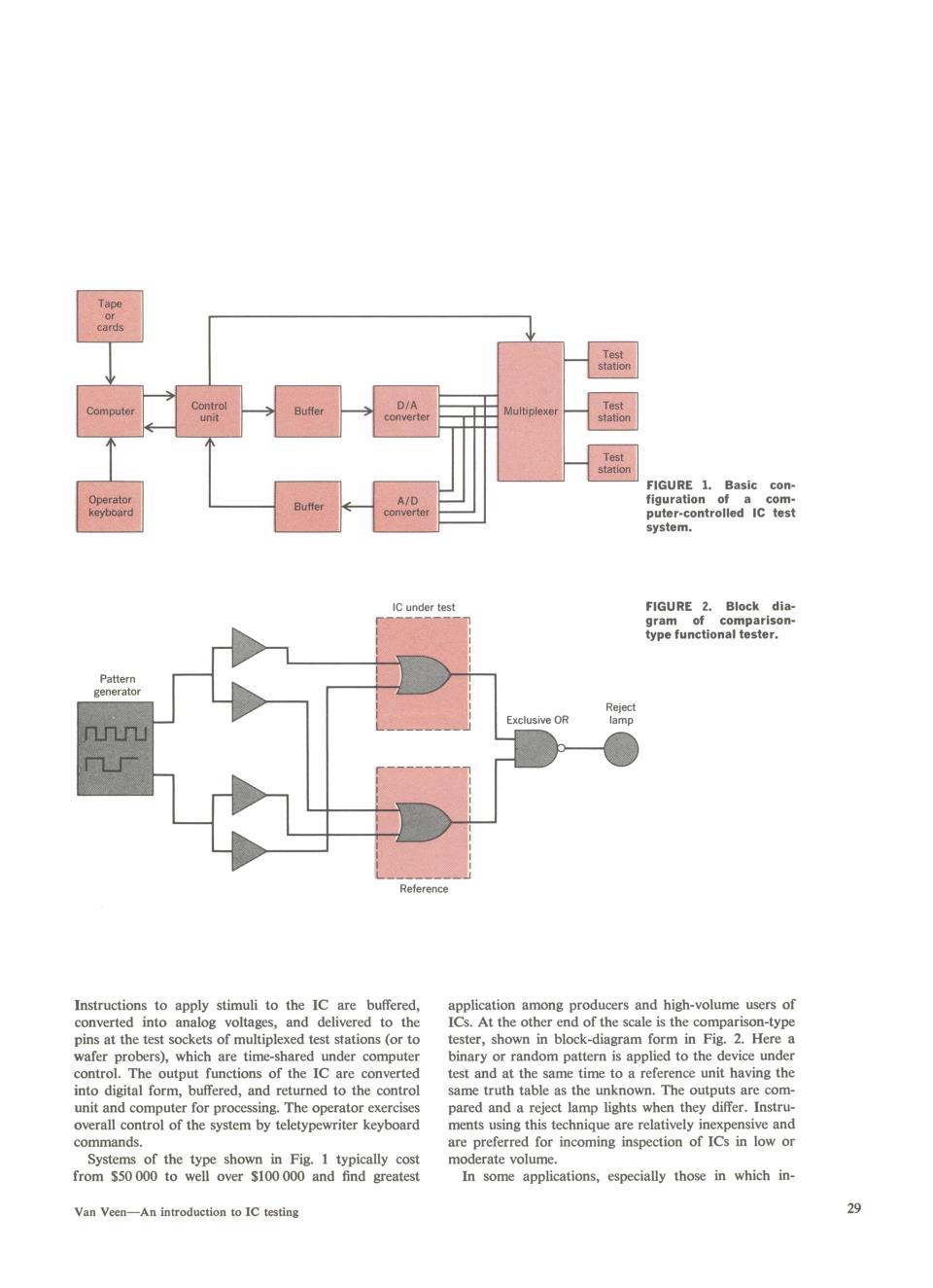
Tape or cards Test statlor Computer Control Buffer D/A Multiplexe Test unit converter station Test station FIGURE 1.Basic con- Operator A/D figuration of a com- keyboard Buffer converte puter-controlled IC test system. IC under test FIGURE 2.Block dia- gram of comparison- type functional tester. Pattern generator Reject Exclusive OR lamp Π几u Instructions to apply stimuli to the IC are buffered, application among producers and high-volume users of converted into analog voltages,and delivered to the ICs.At the other end of the scale is the comparison-type pins at the test sockets of multiplexed test stations (or to tester,shown in block-diagram form in Fig.2.Here a wafer probers),which are time-shared under computer binary or random pattern is applied to the device under control.The output functions of the IC are converted test and at the same time to a reference unit having the into digital form,buffered,and returned to the control same truth table as the unknown.The outputs are com- unit and computer for processing.The operator exercises pared and a reject lamp lights when they differ.Instru- overall control of the system by teletypewriter keyboard ments using this technique are relatively inexpensive and commands. are preferred for incoming inspection of ICs in low or Systems of the type shown in Fig.1 typically cost moderate volume. from S50 000 to well over $100 000 and find greatest In some applications,especially those in which in- Van Veen-An introduction to IC testing 29FIGURE 1. Basic configuration of a computer-controlled IC test system. IC under test FIGURE 2. Block diagram of comparisontype functional tester. Pattern r Il*l * e r l l | | ~~~~~~~~~~~Exclusive OR Rlamrnpt Reference Instructions to apply stimuli to the IC are buffered, application among producers and high-volume users of converted into analog voltages, and delivered to the ICs. At the other end of the scale is the comparison-type pins at the test sockets of multiplexed test stations (or to tester, shown in block-diagram form in Fig. 2. Here a wafer probers), which are time-shared under computer binary or random pattern is applied to the device under control. The output functions of the IC are converted test and at the same time to a reference unit having the into digital form, buffered, and returned to the control same truth table as the unknown. The outputs are comunit and computer for processing. The operator exercises pared and a reject lamp lights when they differ. Instruoverall control of the system by teletypewriter keyboard ments using this technique are relatively inexpensive and commands. are preferred for incoming inspection of ICs in low or Systems of the type shown in Fig. 1 typically cost moderate volume. from $50 000 to well over $100 000 and find greatest In some applications, especially those in which inVan Veen-An introduction to IC testing 29