正在加载图片...

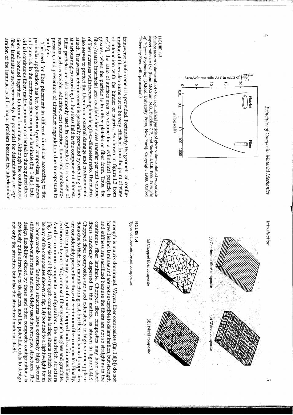
sunlight. FIGURE 1.3 aration of the laminae,is still a major problem because the interlaminar fiber laminate is used extensively,the potential for delamination,or sep- tions and bonded together to form a laminate.Although the continuous vidual continuous fiber/matrix laminae are oriented in the required direc- in figure 1.4.In the continuous fiber composite laminate(fig.1.4[al),indi- particular application has led to various types of composites,as shown The need for fiber placement in different directions according to the pression,and prevention of ultraviolet degradation due to exposure to reasons such as weight reduction,cost reduction,flame and smoke sup- Filler particles are also commonly used in composites for a variety of at various angles according to the stress field in the component of interest. attack.Transverse reinforcement is generally provided by orienting fibers also serves to protect the fibers from external damage and environmental of fiber increases with increasing fiber length-to-diameter ratio.The matrix fiber/matrix interfacial area available for stress transfer per unit volume greatest when the particle is in either platelet or fiber form.Thus,the ref.[7],the ratio of surface area to volume for a cylindrical particle is of interaction with the binder or matrix.As shown in figure 1.3 from uration of fibers also turns out to be very efficient from the point of view transverse reinforcement is provided.Fortunately,the geometrical config- University Press with permission.) aspect ratio=1/d.(From McCrum,N.G.Buckley,C.P,and Bucknall,C.B.1988.Principles of Polymer Engineering [Oxford University Press,New York].Copyright 1988,Oxford Surface area-to-volume ratio A/Vof a cylindrical particle of given volume plotted vs.particle Area/volume ratio A/Vin units of 13 0.01 a (log scale) 10 1001000 Fiber Principles of Composite Material Mechanics FIGURE 1.4 not only the structure but also the structural material itself. (a)Contint Introduction obviously quite attractive to designers,and the potential exists to design design flexibility offered by these and other composite configurations is stiffness-to-weight ratios and are widely used in aerospace structures.The or honeycomb core.Sandwich structures have extremely high flexural be any of the composites shown in fig.1.4)bonded to a lightweight foam (fig.1.5),consists of high-strength composite facing sheets(which could Another common composite configuration,the sandwich structure as shown in figure 1.4(d),or mixed fiber types such as glass and graphite. hybrid composites may consist of mixed chopped and continuous fibers, are considerably poorer than those of continuous fiber composites.Finally, tions due to their low manufacturing cost,but their mechanical properties Chopped fiber composites are used extensively in high-volume applica- fibers randomly dispersed in the matrix,as shown in figure 1.4(c). continuous fiber laminate.Chopped fiber composites may have short and stiffness are sacrificed because the fibers are not so straight as in the have distinct laminae and are not susceptible to delamination,but strength strength is matrix dominated.Woven fiber composites(fig.1.4[b])do not Types of fiber-reinforced composites. (c)Chopped fiber composite (d)Hybrid composite