正在加载图片...
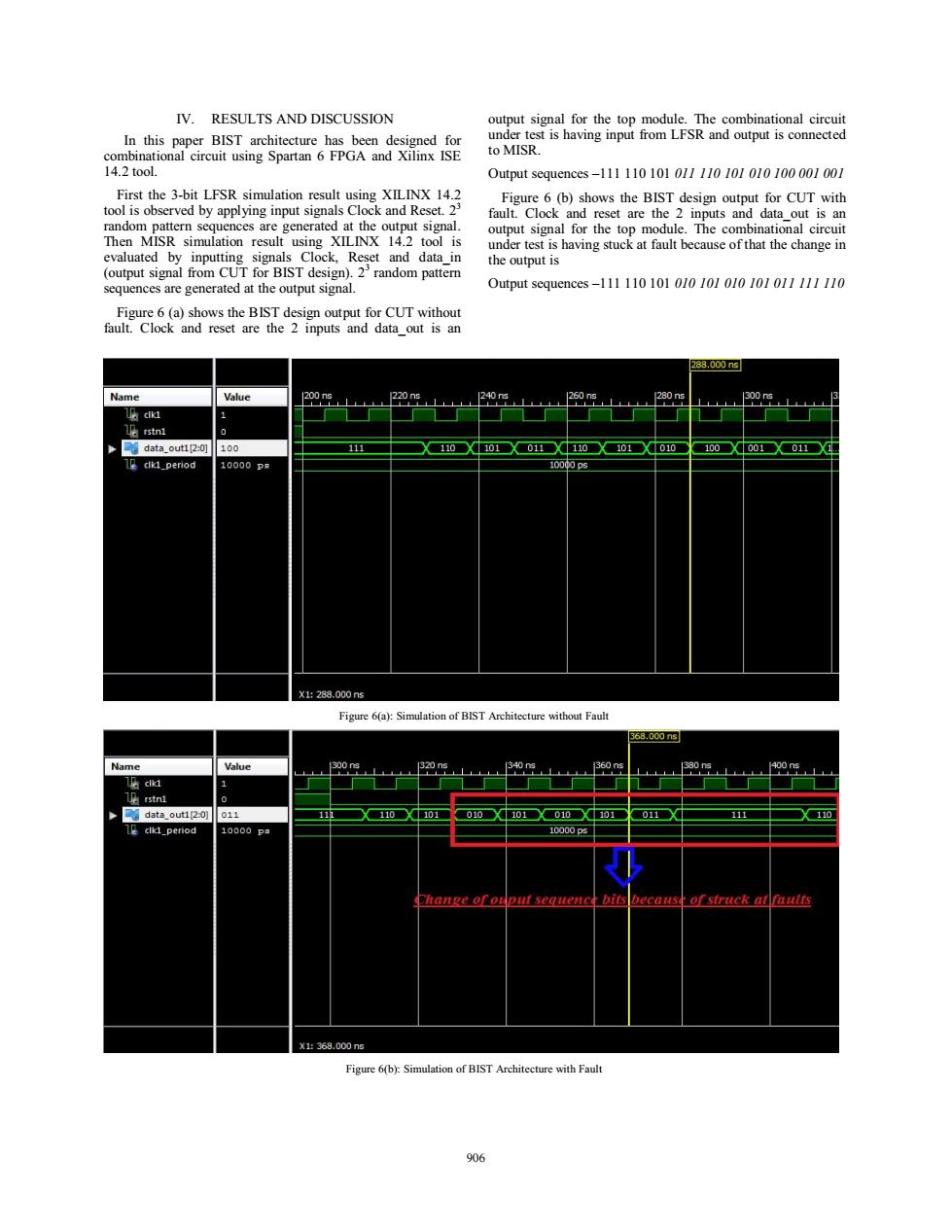
IV.RESULTS AND DISCUSSION output signal for the top module.The combinational circuit In this paper BIST architecture has been designed for under test is having input from LFSR and output is connected combinational circuit using Spartan 6 FPGA and Xilinx ISE to MISR. 14.2 tool. Output sequences-111110101011110101010100001001 First the 3-bit LFSR simulation result using XILINX 14.2 Figure 6(b)shows the BIST design output for CUT with tool is observed by applying input signals Clock and Reset.23 fault.Clock and reset are the 2 inputs and data out is an random pattern sequences are generated at the output signal. output signal for the top module.The combinational circuit Then MISR simulation result using XILINX 14.2 tool is under test is having stuck at fault because of that the change in evaluated by inputting signals Clock,Reset and data in the output is (output signal from CUT for BIST design).23random pattern sequences are generated at the output signal. Output sequences-11111010101010l010101011111110 Figure 6(a)shows the BIST design output for CUT without fault.Clock and reset are the 2 inputs and data out is an 288.000n3 Name Value 200ns 220ns Le rstni data_outi2:0] 100 111 110X101X011X110X101X010■ 100X001X011X1 Le clkl_period 10000P 1000ps X1288.000ns Figure 6(a):Simulation of BIST Architecture without Fault 568.000n9 Name Value 300 ns 1320ns 340s 360ns 380n 400ns 1 0 data_out1[2:0] 011 0X110●X4101 010101010○101 011○X0 111 ●X110 clikd_period 10000P 10000p5 Change of ouput sequence bits because of struck at faults X1:368.000ns Figure 6(b):Simulation of BIST Architecture with Fault 906IV. RESULTS AND DISCUSSION In this paper BIST architecture has been designed for combinational circuit using Spartan 6 FPGA and Xilinx ISE 14.2 tool. First the 3-bit LFSR simulation result using XILINX 14.2 tool is observed by applying input signals Clock and Reset. 23 random pattern sequences are generated at the output signal. Then MISR simulation result using XILINX 14.2 tool is evaluated by inputting signals Clock, Reset and data_in (output signal from CUT for BIST design). 23 random pattern sequences are generated at the output signal. Figure 6 (a) shows the BIST design output for CUT without fault. Clock and reset are the 2 inputs and data_out is an output signal for the top module. The combinational circuit under test is having input from LFSR and output is connected to MISR. Output sequences –111 110 101 011 110 101 010 100 001 001 Figure 6 (b) shows the BIST design output for CUT with fault. Clock and reset are the 2 inputs and data_out is an output signal for the top module. The combinational circuit under test is having stuck at fault because of that the change in the output is Output sequences –111 110 101 010 101 010 101 011 111 110 Figure 6(a): Simulation of BIST Architecture without Fault Figure 6(b): Simulation of BIST Architecture with Fault 906