正在加载图片...
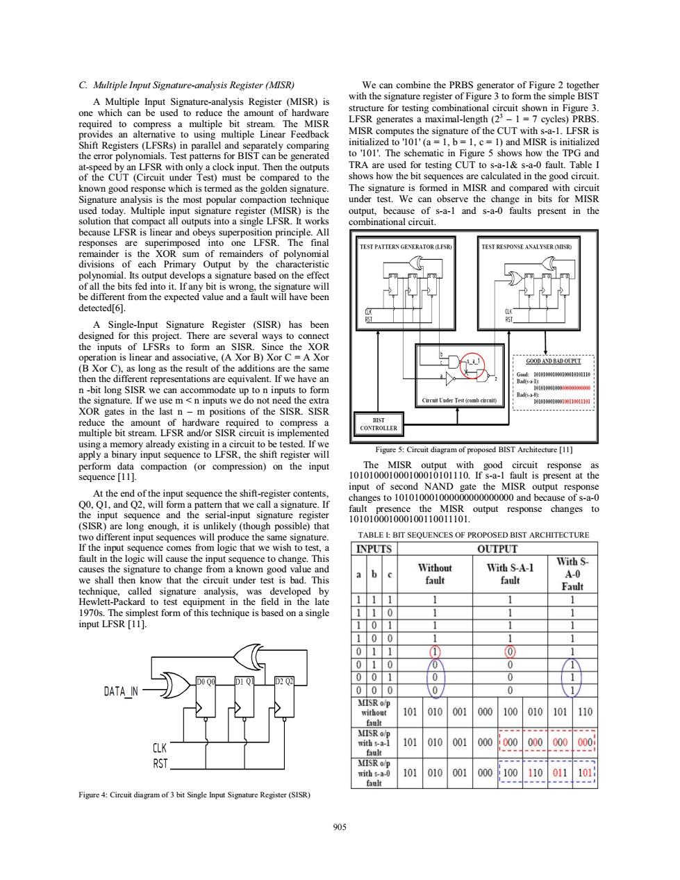
C.Multiple Input Signature-analysis Register (MISR) We can combine the PRBS generator of Figure 2 together A Multiple Input Signature-analysis Register (MISR)is with the signature register of Figure 3 to form the simple BIST one which can be used to reduce the amount of hardware structure for testing combinational circuit shown in Figure 3 required to compress a multiple bit stream.The MISR LFSR generates a maximal-length(22-1 =7 cycles)PRBS provides an alternative to using multiple Linear Feedback MISR computes the signature of the CUT with s-a-1.LFSR is Shift Registers(LFSRs)in parallel and separately comparing initialized to '101'(a 1,b=1.c=1)and MISR is initialized the error polynomials.Test patterns for BIST can be generated to '101'.The schematic in Figure 5 shows how the TPG and at-speed by an LFSR with only a clock input.Then the outputs TRA are used for testing CUT to s-a-1&s-a-0 fault.Table I of the CUT (Circuit under Test)must be compared to the shows how the bit sequences are calculated in the good circuit. known good response which is termed as the golden signature. The signature is formed in MISR and compared with circuit Signature analysis is the most popular compaction technique under test.We can observe the change in bits for MISR used today.Multiple input signature register (MISR)is the output, because of s-a-1 and s-a-0 faults present in the solution that compact all outputs into a single LFSR.It works combinational circuit because LFSR is linear and obeys superposition principle.All responses are superimposed into one LFSR.The final TEST PATTERN GENERATOR (LFSR) TEST RESPONSE ANALYSER OMUISR) remainder is the XOR sum of remainders of polynomial divisions of each Primary Output by the characteristic polynomial.Its output develops a signature based on the effect of all the bits fed into it.If any bit is wrong,the signature will be different from the expected value and a fault will have been detected[6]. A Single-Input Signature Register (SISR)has been designed for this project.There are several ways to connect the inputs of LFSRs to form an SISR.Since the XOR operation is linear and associative,(A Xor B)Xor C=A Xor GOOD AND BADOUPUI (B Xor C),as long as the result of the additions are the same 9+1010U00310601000]0101110 then the different representations are equivalent.If we have an n-bit long SISR we can accommodate up to n inputs to form 0101010006 the signature.If we use m n inputs we do not need the extra Circmit Uader Test (comb circuit) 010001001o110011101 XOR gates in the last n-m positions of the SISR.SISR reduce the amount of hardware required to compress a multiple bit stream.LFSR and/or SISR circuit is implemented using a memory already existing in a circuit to be tested.If we apply a binary input sequence to LFSR,the shift register will Figure 5:Circuit diagram of proposed BIST Architecture [11] perform data compaction (or compression)on the input The MISR output with good circuit response as sequence [11] 101010001000100010101110.If s-a-1 fault is present at the input of second NAND gate the MISR output response At the end of the input sequence the shift-register contents, Q0,Q1,and Q2,will form a pattern that we call a signature.If changes to 101010001000000000000000 and because of s-a-0 fault presence the MISR output response changes to the input sequence and the serial-input signature register 101010001000100110011101 (SISR)are long enough,it is unlikely (though possible)that two different input sequences will produce the same signature. TABLE L BIT SEQUENCES OF PROPOSED BIST ARCHITECTURE If the input sequence comes from logic that we wish to test,a INPUTS OUTPUT fault in the logic will cause the input sequence to change.This With S causes the signature to change from a known good value and Without With S-A-1 b A-0 we shall then know that the circuit under test is bad.This fault fault technique,called signature analysis,was developed by Fault Hewlett-Packard to test equipment in the field in the late 1 1 1 1 1970s.The simplest form of this technique is based on a single input LFSR [11]. 0 1 1 1 00 1 0 (1) O 0 0 0 0 D000 D202 00 0 0 1 DATA IN 000 0 0 1 MISR o/p without 101 010 001 000 100 010 101 110 fault MISR o/p CLK with s-a-l 101 010 001 000 i000 000 000 000 tault RST MISR o/p with sa-0 101 010 001 000 100 110 011 101 fault Figure 4:Circuit diagram of 3 bit Single Input Signature Register(SISR) 905C. Multiple Input Signature-analysis Register (MISR) A Multiple Input Signature-analysis Register (MISR) is one which can be used to reduce the amount of hardware required to compress a multiple bit stream. The MISR provides an alternative to using multiple Linear Feedback Shift Registers (LFSRs) in parallel and separately comparing the error polynomials. Test patterns for BIST can be generated at-speed by an LFSR with only a clock input. Then the outputs of the CUT (Circuit under Test) must be compared to the known good response which is termed as the golden signature. Signature analysis is the most popular compaction technique used today. Multiple input signature register (MISR) is the solution that compact all outputs into a single LFSR. It works because LFSR is linear and obeys superposition principle. All responses are superimposed into one LFSR. The final remainder is the XOR sum of remainders of polynomial divisions of each Primary Output by the characteristic polynomial. Its output develops a signature based on the effect of all the bits fed into it. If any bit is wrong, the signature will be different from the expected value and a fault will have been detected[6]. A Single-Input Signature Register (SISR) has been designed for this project. There are several ways to connect the inputs of LFSRs to form an SISR. Since the XOR operation is linear and associative, (A Xor B) Xor C = A Xor (B Xor C), as long as the result of the additions are the same then the different representations are equivalent. If we have an n -bit long SISR we can accommodate up to n inputs to form the signature. If we use m < n inputs we do not need the extra XOR gates in the last n – m positions of the SISR. SISR reduce the amount of hardware required to compress a multiple bit stream. LFSR and/or SISR circuit is implemented using a memory already existing in a circuit to be tested. If we apply a binary input sequence to LFSR, the shift register will perform data compaction (or compression) on the input sequence [11]. At the end of the input sequence the shift-register contents, Q0, Q1, and Q2, will form a pattern that we call a signature. If the input sequence and the serial-input signature register (SISR) are long enough, it is unlikely (though possible) that two different input sequences will produce the same signature. If the input sequence comes from logic that we wish to test, a fault in the logic will cause the input sequence to change. This causes the signature to change from a known good value and we shall then know that the circuit under test is bad. This technique, called signature analysis, was developed by Hewlett-Packard to test equipment in the field in the late 1970s. The simplest form of this technique is based on a single input LFSR [11]. Figure 4: Circuit diagram of 3 bit Single Input Signature Register (SISR) We can combine the PRBS generator of Figure 2 together with the signature register of Figure 3 to form the simple BIST structure for testing combinational circuit shown in Figure 3. LFSR generates a maximal-length (23 – 1 = 7 cycles) PRBS. MISR computes the signature of the CUT with s-a-1. LFSR is initialized to '101' (a = 1, b = 1, c = 1) and MISR is initialized to '101'. The schematic in Figure 5 shows how the TPG and TRA are used for testing CUT to s-a-1& s-a-0 fault. Table I shows how the bit sequences are calculated in the good circuit. The signature is formed in MISR and compared with circuit under test. We can observe the change in bits for MISR output, because of s-a-1 and s-a-0 faults present in the combinational circuit. Figure 5: Circuit diagram of proposed BIST Architecture [11] The MISR output with good circuit response as 101010001000100010101110. If s-a-1 fault is present at the input of second NAND gate the MISR output response changes to 101010001000000000000000 and because of s-a-0 fault presence the MISR output response changes to 101010001000100110011101. TABLE I: BIT SEQUENCES OF PROPOSED BIST ARCHITECTURE 905