正在加载图片...
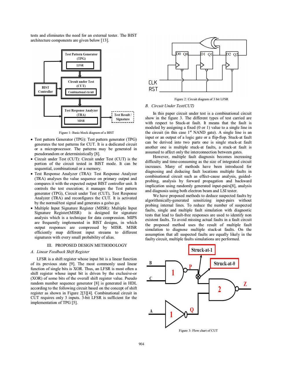
tests and eliminates the need for an external tester.The BIST architecture components are given below [131. Test Pattern Generator (TPG) LFSR Circuit under Test CLK BIST (CUT) Controller RST Combinational circuit Figure 2:Circuit diagram of 3 bit LFSR B.Circuit Under Test(CUT) Test Response Analyzer (TRA) T- Test Result/ In this paper circuit under test is a combinational circuit MISR Signature show in the figure 3.The different types of test carried are with respect to Stuck-at fault.It means that the fault is modeled by assigning a fixed(0 or 1)value to a single line in Figure 1:Basic block diagram of a BIST the circuit (in this case 1s NAND gate).A single line is an Test pattern Generator(TPG):Test pattern generator (TPG) input or an output of a logic gate or a flip-flop.Stuck-at fault generates the test patterns for CUT.It is a dedicated circuit can be derived into two parts one is single stuck-at fault or a microprocessor.The patterns may be generated in another one is multiple stuck-at faults,a stuck-at fault is pseudorandom or deterministically [8]. assumed to affect only the interconnection between gates. Circuit under Test(CUT):Circuit under Test(CUT)is the However,multiple fault diagnosis becomes increasing portion of the circuit tested in BIST mode.It can be difficulty and time-consuming as the size of integrated circuit sequential,combinational or a memory. increases.Many of methods have been introduced for Test Response Analyzer(TRA):Test Response Analyzer diagnosing and deducing fault locations multiple faults in (TRA)analyses the value sequence on primary output and combinational circuit such as effect-cause analysis,guided- compares it with the expected output BIST controller unit.It probing,analysis by forward propagation and backward controls the test execution;it manages the Test pattern implication using randomly generated input-pairs[8],analysis and diagnosis using both electron beam and LSI tester. generator (TPG),Circuit under Test (CUT),Test Response Analyzer (TRA)and reconfigures the CUT.It is activated We have proposed methods to deduce suspected faults by algorithmically-generated sensitizing input-pairs without by the normal/test signal and generates a go/no go. probing internal lines.To reduce the number of suspected Multiple Input Signature Register(MISR):Multiple Input faults,single and multiple fault simulation with diagnostic Signature Register(MISR)is designed for signature tests that lead to fault-free responses are used to identify non analysis which is a technique for data compression.MIPS are frequently implemented in BIST designs,in which existent faults.To avoid missing actual faults in a fault circuit output responses are compressed by MISR.MISR the proposed method uses the result of multiple fault simulation to diagnose multiple stuck-at faults.On the efficiently map different input streams to different signatures with every small probability of alias. assumption that all suspected faults are equally likely in the faulty circuit,multiple faults simulations are performed. IIL.PROPOSED DESIGN METHODOLOGY A.Linear Feedback Shift Register Struck-at-1 LFSR is a shift register whose input bit is a linear function of its previous state [9].The most commonly used linear Struck-at-0 function of single bits is XOR.Thus,an LFSR is most often a shift register whose input bit is driven by the exclusive-or (XOR)of some bits of the overall shift register value.Pseudo random number sequence generator [8]is generated in HDL according to the following circuit based on the concept of shift register as shown in Figure 2[3][4].Combinational circuit in CUT requires only 3 inputs.3-bit LFSR is sufficient for the implementation of TPG [5]. Figure 3:Flow chart of CUT 904tests and eliminates the need for an external tester. The BIST architecture components are given below [13]. Figure 1: Basic block diagram of a BIST • Test pattern Generator (TPG): Test pattern generator (TPG) generates the test patterns for CUT. It is a dedicated circuit or a microprocessor. The patterns may be generated in pseudorandom or deterministically [8]. • Circuit under Test (CUT): Circuit under Test (CUT) is the portion of the circuit tested in BIST mode. It can be sequential, combinational or a memory. • Test Response Analyzer (TRA): Test Response Analyzer (TRA) analyses the value sequence on primary output and compares it with the expected output BIST controller unit. It controls the test execution; it manages the Test pattern generator (TPG), Circuit under Test (CUT), Test Response Analyzer (TRA) and reconfigures the CUT. It is activated by the normal/test signal and generates a go/no go. • Multiple Input Signature Register (MISR): Multiple Input Signature Register(MISR) is designed for signature analysis which is a technique for data compression. MIPS are frequently implemented in BIST designs, in which output responses are compressed by MISR. MISR efficiently map different input streams to different signatures with every small probability of alias. III. PROPOSED DESIGN METHODOLOGY A. Linear Feedback Shift Register LFSR is a shift register whose input bit is a linear function of its previous state [9]. The most commonly used linear function of single bits is XOR. Thus, an LFSR is most often a shift register whose input bit is driven by the exclusive-or (XOR) of some bits of the overall shift register value. Pseudo random number sequence generator [8] is generated in HDL according to the following circuit based on the concept of shift register as shown in Figure 2[3][4]. Combinational circuit in CUT requires only 3 inputs. 3-bit LFSR is sufficient for the implementation of TPG [5]. Figure 2: Circuit diagram of 3 bit LFSR B. Circuit Under Test(CUT) In this paper circuit under test is a combinational circuit show in the figure 3. The different types of test carried are with respect to Stuck-at fault. It means that the fault is modeled by assigning a fixed (0 or 1) value to a single line in the circuit (in this case 1st NAND gate). A single line is an input or an output of a logic gate or a flip-flop. Stuck-at fault can be derived into two parts one is single stuck-at fault another one is multiple stuck-at faults, a stuck-at fault is assumed to affect only the interconnection between gates. However, multiple fault diagnosis becomes increasing difficulty and time-consuming as the size of integrated circuit increases. Many of methods have been introduced for diagnosing and deducing fault locations multiple faults in combinational circuit such as effect-cause analysis, guidedprobing, analysis by forward propagation and backward implication using randomly generated input-pairs[8], analysis and diagnosis using both electron beam and LSI tester. We have proposed methods to deduce suspected faults by algorithmically-generated sensitizing input-pairs without probing internal lines. To reduce the number of suspected faults, single and multiple fault simulation with diagnostic tests that lead to fault-free responses are used to identify non existent faults. To avoid missing actual faults in a fault circuit the proposed method uses the result of multiple fault simulation to diagnose multiple stuck-at faults. On the assumption that all suspected faults are equally likely in the faulty circuit, multiple faults simulations are performed. Figure 3: Flow chart of CUT 904