正在加载图片...
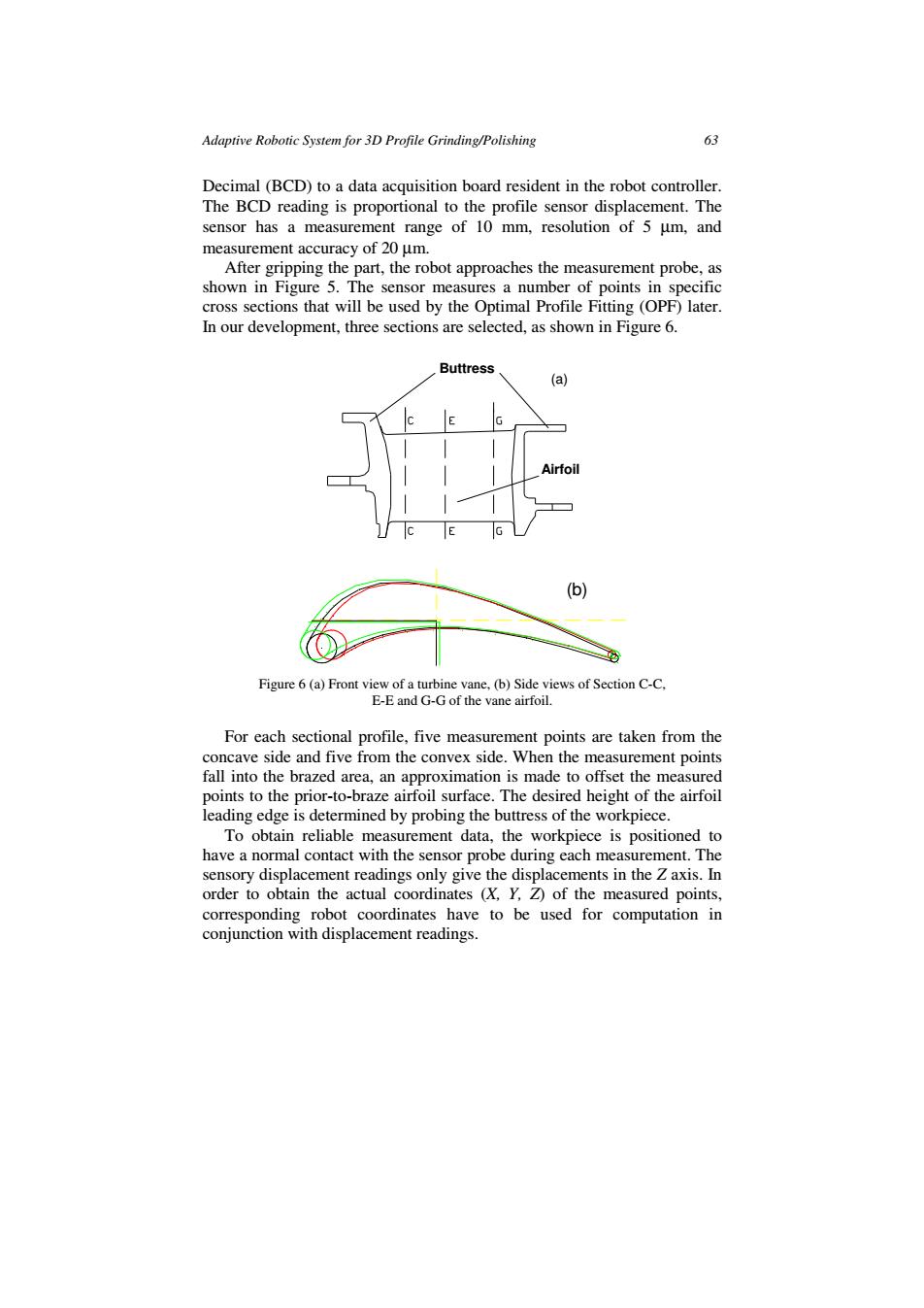
Adaptive Robotic System for 3D Profile Grinding/Polishing 63 Decimal (BCD)to a data acquisition board resident in the robot controller. The BCD reading is proportional to the profile sensor displacement.The sensor has a measurement range of 10 mm,resolution of 5 um,and measurement accuracy of 20 um. After gripping the part,the robot approaches the measurement probe,as shown in Figure 5.The sensor measures a number of points in specific cross sections that will be used by the Optimal Profile Fitting(OPF)later. In our development,three sections are selected,as shown in Figure 6. Buttress (a) (b) Figure 6(a)Front view of a turbine vane,(b)Side views of Section C-C. E-E and G-G of the vane airfoil. For each sectional profile,five measurement points are taken from the concave side and five from the convex side.When the measurement points fall into the brazed area,an approximation is made to offset the measured points to the prior-to-braze airfoil surface.The desired height of the airfoil leading edge is determined by probing the buttress of the workpiece. To obtain reliable measurement data,the workpiece is positioned to have a normal contact with the sensor probe during each measurement.The sensory displacement readings only give the displacements in the Z axis.In order to obtain the actual coordinates (X,Y,Z)of the measured points, corresponding robot coordinates have to be used for computation in conjunction with displacement readings.Adaptive Robotic System for 3D Profile Grinding/Polishing 63 Decimal (BCD) to a data acquisition board resident in the robot controller. The BCD reading is proportional to the profile sensor displacement. The sensor has a measurement range of 10 mm, resolution of 5 µm, and measurement accuracy of 20 µm. After gripping the part, the robot approaches the measurement probe, as shown in Figure 5. The sensor measures a number of points in specific cross sections that will be used by the Optimal Profile Fitting (OPF) later. In our development, three sections are selected, as shown in Figure 6. Buttress Airfoil (a) (b) Figure 6 (a) Front view of a turbine vane, (b) Side views of Section C-C, E-E and G-G of the vane airfoil. For each sectional profile, five measurement points are taken from the concave side and five from the convex side. When the measurement points fall into the brazed area, an approximation is made to offset the measured points to the prior-to-braze airfoil surface. The desired height of the airfoil leading edge is determined by probing the buttress of the workpiece. To obtain reliable measurement data, the workpiece is positioned to have a normal contact with the sensor probe during each measurement. The sensory displacement readings only give the displacements in the Z axis. In order to obtain the actual coordinates (X, Y, Z) of the measured points, corresponding robot coordinates have to be used for computation in conjunction with displacement readings