正在加载图片...
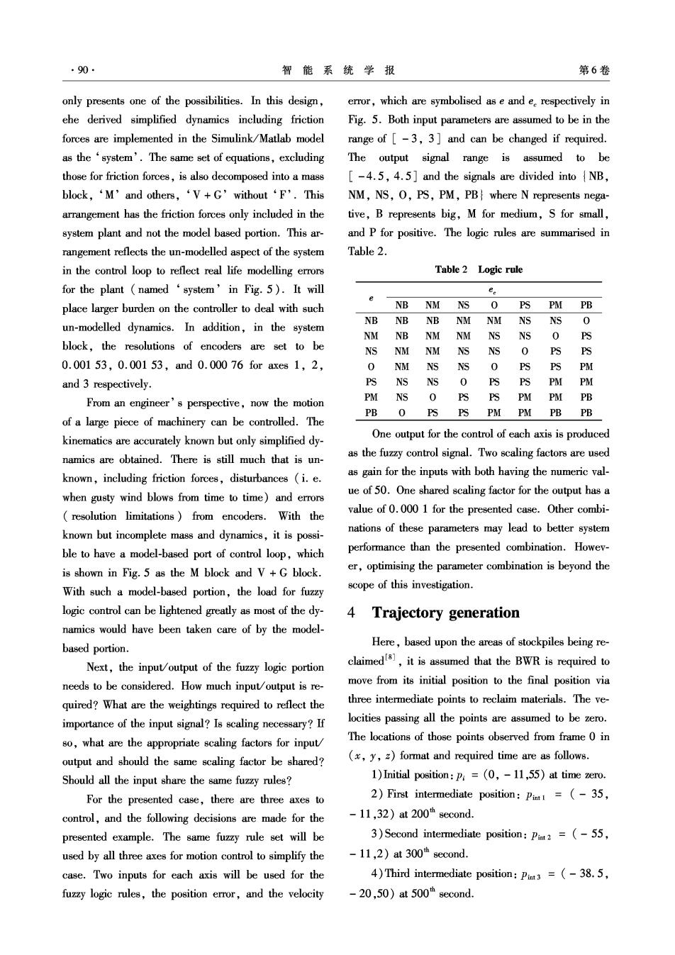
90 智能系统学报 第6卷 only presents one of the possibilities.In this design, error,which are symbolised as e and e respectively in ehe derived simplified dynamics including friction Fig.5.Both input parameters are assumed to be in the forces are implemented in the Simulink/Matlab model range of [-3,3]and can be changed if required. as the 'system'.The same set of equations,excluding The output signal range is assumed to be those for friction forces,is also decomposed into a mass [-4.5,4.5]and the signals are divided into NB, block,‘M'and others,‘V+G'without‘F'.This NM,NS,O,PS,PM,PB where N represents nega- arrangement has the friction forces only included in the tive,B represents big,M for medium,S for small, system plant and not the model based portion.This ar- and P for positive.The logic rules are summarised in rangement reflects the un-modelled aspect of the system Table 2. in the control loop to reflect real life modelling errors Table 2 Logic rule for the plant(named‘system'in Fig.5).It will ee place larger burden on the controller to deal with such NB NM NS 0 PS PM PB NB un-modelled dynamics.In addition,in the system NB NB NM NM NSNS 0 NM NB nm NM NSNS 0 PS block,the resolutions of encoders are set to be NS NM NM NS NS 0 PS PS 0.00153,0.00153,and0.00076 for axes1,2, 0 NM NS NS 0 PS PS PM and 3 respectively. PS NS NS 0 PS PS PM PM From an engineer's perspective,now the motion PM NS 0 PS PS PM PM PB PB O PSPS PM PM PB PB of a large piece of machinery can be controlled.The kinematics are accurately known but only simplified dy- One output for the control of each axis is produced namics are obtained.There is still much that is un- as the fuzzy control signal.Two scaling factors are used known,including friction forces,disturbances (i.e. as gain for the inputs with both having the numeric val- when gusty wind blows from time to time)and errors ue of 50.One shared scaling factor for the output has a resolution limitations)from encoders.With the value of 0.000 1 for the presented case.Other combi- known but incomplete mass and dynamics,it is possi- nations of these parameters may lead to better system ble to have a model-based port of control loop,which performance than the presented combination.Howev- is shown in Fig.5 as the M block and V+G block. er,optimising the parameter combination is beyond the With such a model-based portion,the load for fuzzy scope of this investigation. logic control can be lightened greatly as most of the dy- 4 Trajectory generation namics would have been taken care of by the model- based portion. Here,based upon the areas of stockpiles being re- Next,the input/output of the fuzzy logic portion claimeds,it is assumed that the BWR is required to needs to be considered.How much input/output is re- move from its initial position to the final position via quired?What are the weightings required to reflect the three intermediate points to reclaim materials.The ve- importance of the input signal?Is scaling necessary?If locities passing all the points are assumed to be zero. so,what are the appropriate scaling factors for input The locations of those points observed from frame 0 in output and should the same scaling factor be shared? (x,y,z)format and required time are as follows. Should all the input share the same fuzzy rules? 1)Initial position:P=(0,-11,55)at time zero. For the presented case,there are three axes to 2)First intermediate position:Pit=(-35, control,and the following decisions are made for the -11,32)at200"second. presented example.The same fuzzy rule set will be 3)Second intermediate position:Pimt2 =(-55, used by all three axes for motion control to simplify the -11,2)at 300h second. case.Two inputs for each axis will be used for the 4)Third intermediate position:Pit3=(-38.5, fuzzy logic rules,the position error,and the velocity -20,50)a500"second