正在加载图片...
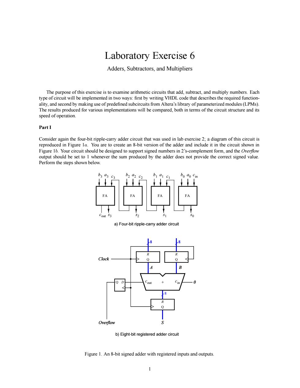
Laboratory Exercise 6 Adders,Subtractors,and Multipliers The purpose of this exercise is to examine arithmetic circuits that add,subtract,and multiply numbers.Each be implemented in t ways.nrst by de th describes the requr ules ared.bothin terms of the eircuit structure and its speed of operation. PartI Consider again the four-bit ripple-carry adder circuit that was used in lab exercise 2.a diagram of this circuit is ps shown below 当口学日 a)Four-bit ripple-carry adder circuit e时d b)Eight-bitregistered adder circui Figure 1.An8-bit signed adder with registered inputs and outputs Laboratory Exercise 6 Adders, Subtractors, and Multipliers The purpose of this exercise is to examine arithmetic circuits that add, subtract, and multiply numbers. Each type of circuit will be implemented in two ways: first by writing VHDL code that describes the required functionality, and second by making use of predefined subcircuits from Altera’s library of parameterized modules (LPMs). The results produced for various implementations will be compared, both in terms of the circuit structure and its speed of operation. Part I Consider again the four-bit ripple-carry adder circuit that was used in lab exercise 2; a diagram of this circuit is reproduced in Figure 1a. You are to create an 8-bit version of the adder and include it in the circuit shown in Figure 1b. Your circuit should be designed to support signed numbers in 2’s-complement form, and the Overflow output should be set to 1 whenever the sum produced by the adder does not provide the correct signed value. Perform the steps shown below. + A S 8 8 8 B R Q R Q R Q cout cin Q D 0 Overflow Clock FA a0 b0 s0 FA c1 a1 b1 s1 FA c2 a2 b2 s2 FA c3 a3 b3 s3 cout a) Four-bit ripple-carry adder circuit cin + A S 8 8 B R Q R Q R Q Q D 0 Overflow Clock cin cout b) Eight-bit registered adder circuit Figure 1. An 8-bit signed adder with registered inputs and outputs. 1