正在加载图片...

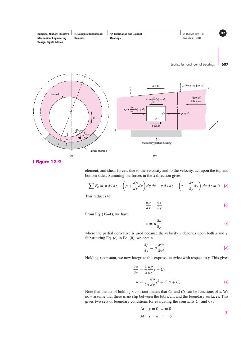
Budynas-Nisbett:Shigley's Ill.Design of Mechanical 12.Lubrication and Journal T©The McGraw-Hil 607 Mechanical Engineering Elements Bearings Companies,2008 Design,Eighth Edition Lubrication and Joumnal Bearings 607 u=U Rotating journal (口+肛d)血k Flow of lubricant (p+ pddk d r dx dz Stationary partial bushing Partial bushing (a) (b) I Figure 12-9 element,and shear forces,due to the viscosity and to the velocity,act upon the top and bottom sides.Summing the forces in the x direction gives ∑E=pdydz-(p+e ar dy dpdx dy di-rdxdz++a dx dz=0 (a) This reduces to dp a y (6 dx From Eq.(12-1),we have ou t=Hay d where the partial derivative is used because the velocity u depends upon both x and y. Substituting Eq.(c)in Eq.(b),we obtain dp a2u = (d) Holding x constant,we now integrate this expression twice with respect to y.This gives au1dp 亦+G 1d迎y2+Cy+C2 2u dx (e] Note that the act of holding x constant means that Ci and C2 can be functions of x.We now assume that there is no slip between the lubricant and the boundary surfaces.This gives two sets of boundary conditions for evaluating the constants Ci and C2: At y=0,u=0 9 At y=h,u=UBudynas−Nisbett: Shigley’s Mechanical Engineering Design, Eighth Edition III. Design of Mechanical Elements 12. Lubrication and Journal Bearings © The McGraw−Hill 607 Companies, 2008 Lubrication and Journal Bearings 607 dx h U dy Journal (a) (b) Partial bushing dy h z x y dx dx dz p dy dz ∂y ( + dy) dx dz ∂ dx (p + dx) dy dz dp u = U Flow of lubricant Stationary partial bushing Rotating journal element, and shear forces, due to the viscosity and to the velocity, act upon the top and bottom sides. Summing the forces in the x direction gives Fx = pdydz − p + dp dx dx dydz − τ dx dz + τ + ∂τ ∂y dy dx dz = 0 (a) This reduces to dp dx = ∂τ ∂y (b) From Eq. (12–1), we have τ = μ ∂u ∂y (c) where the partial derivative is used because the velocity u depends upon both x and y. Substituting Eq. (c) in Eq. (b), we obtain dp dx = μ ∂2u ∂y2 (d) Holding x constant, we now integrate this expression twice with respect to y. This gives ∂u ∂y = 1 μ dp dx y + C1 u = 1 2μ dp dx y2 + C1 y + C2 (e) Note that the act of holding x constant means that C1 and C2 can be functions of x. We now assume that there is no slip between the lubricant and the boundary surfaces. This gives two sets of boundary conditions for evaluating the constants C1 and C2: At y = 0, u = 0 At y = h, u = U (f ) Figure 12–9����