正在加载图片...

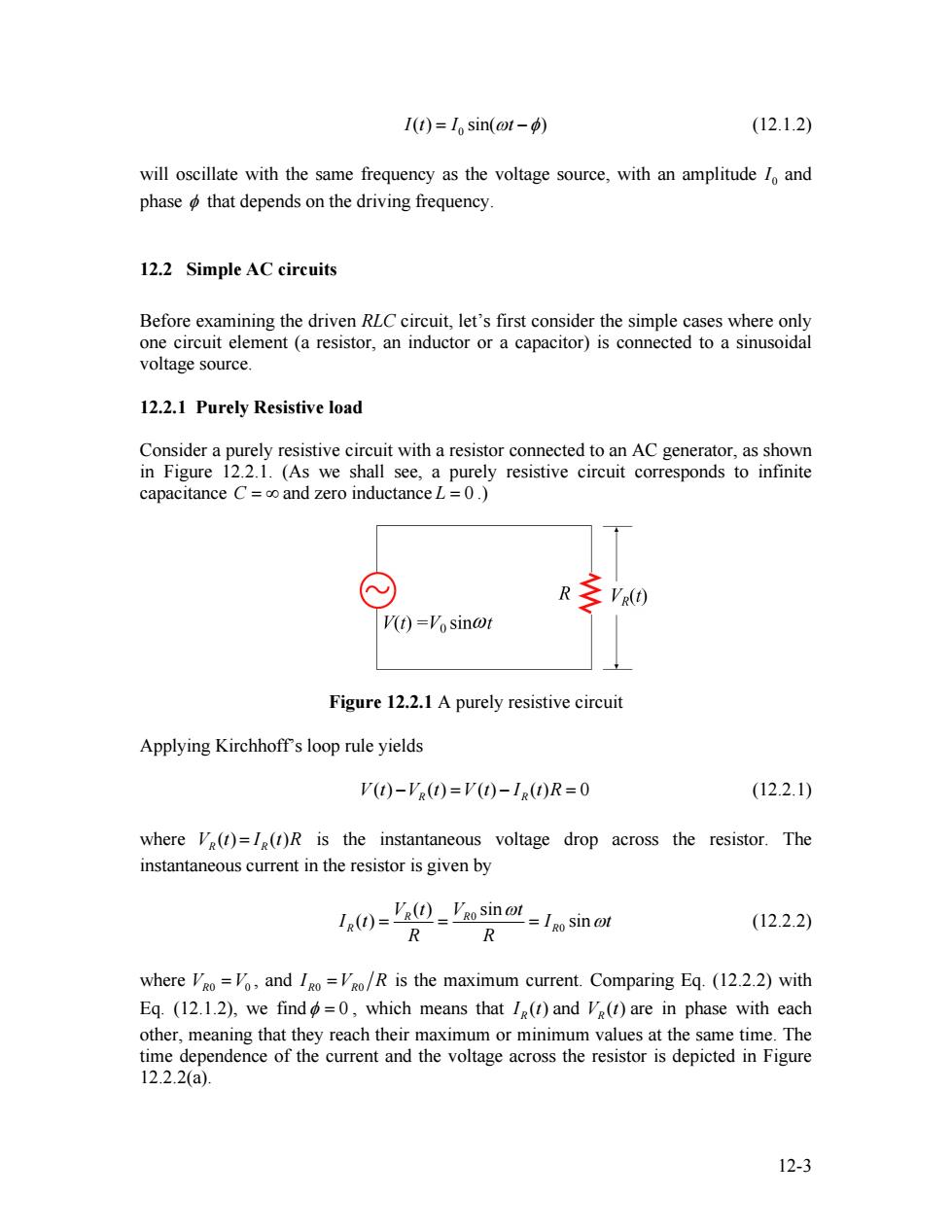
I(t)=lo sin(ot-φ) (12.1.2) will oscillate with the same frequency as the voltage source,with an amplitude lo and phase o that depends on the driving frequency. 12.2 Simple AC circuits Before examining the driven RLC circuit,let's first consider the simple cases where only one circuit element (a resistor,an inductor or a capacitor)is connected to a sinusoidal voltage source. 12.2.1 Purely Resistive load Consider a purely resistive circuit with a resistor connected to an AC generator,as shown in Figure 12.2.1.(As we shall see,a purely resistive circuit corresponds to infinite capacitance C=co and zero inductance L=0.) R VR(O) (t)='osinωt Figure 12.2.1 A purely resistive circuit Applying Kirchhoffs loop rule yields V(t)-V(t)=V(t)-I()R=0 (12.2.1) where Ve(t)=I(t)R is the instantaneous voltage drop across the resistor.The instantaneous current in the resistor is given by (V(Vaosin ot sin ot R (12.2.2) R where VRo =Vo,and Igo=VRo/R is the maximum current.Comparing Eq.(12.2.2)with Eq.(12.1.2),we find=0,which means that I(t)and V(t)are in phase with each other,meaning that they reach their maximum or minimum values at the same time.The time dependence of the current and the voltage across the resistor is depicted in Figure 12.2.2(a). 12-30 I t( ) = I sin(ωt −φ) (12.1.2) will oscillate with the same frequency as the voltage source, with an amplitude 0 I and phase φ that depends on the driving frequency. 12.2 Simple AC circuits Before examining the driven RLC circuit, let’s first consider the simple cases where only one circuit element (a resistor, an inductor or a capacitor) is connected to a sinusoidal voltage source. 12.2.1 Purely Resistive load Consider a purely resistive circuit with a resistor connected to an AC generator, as shown in Figure 12.2.1. (As we shall see, a purely resistive circuit corresponds to infinite capacitance C = ∞ and zero inductance L = 0 .) Figure 12.2.1 A purely resistive circuit Applying Kirchhoff’s loop rule yields ( ) ( ) ( ) ( ) 0 V t VR R − t = − V t I t R = (12.2.1) where is the instantaneous voltage drop across the resistor. The instantaneous current in the resistor is given by ( ) ( ) V t R R = I t R 0 0 ( ) sin ( ) sin R R R V t V t R I t R R I t ω = = = ω (12.2.2) where , and VR0 =V0 R0 R0 I =V R is the maximum current. Comparing Eq. (12.2.2) with Eq. (12.1.2), we findφ = 0 , which means that ( ) RI t and are in phase with each other, meaning that they reach their maximum or minimum values at the same time. The time dependence of the current and the voltage across the resistor is depicted in Figure 12.2.2(a). ( ) VR t 12-3