正在加载图片...

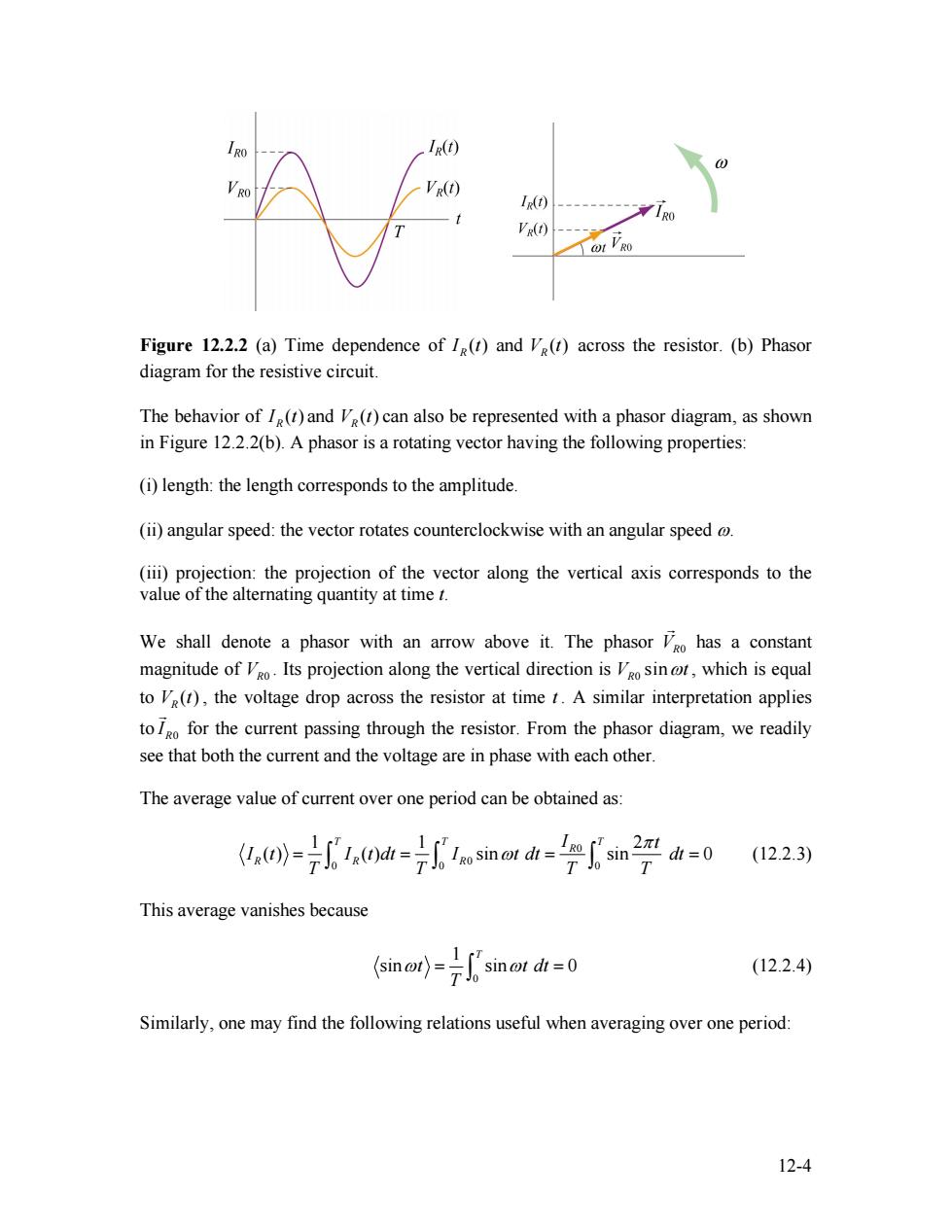
RO IR(t) V RO VR(t) I(t) ----10 VR(A) Figure 12.2.2 (a)Time dependence of I(t)and Ve(t)across the resistor.(b)Phasor diagram for the resistive circuit. The behavior of I(t)and V(t)can also be represented with a phasor diagram,as shown in Figure 12.2.2(b).A phasor is a rotating vector having the following properties: (i)length:the length corresponds to the amplitude. (ii)angular speed:the vector rotates counterclockwise with an angular speed @ (iii)projection:the projection of the vector along the vertical axis corresponds to the value of the alternating quantity at time t. We shall denote a phasor with an arrow above it.The phasor Vgo has a constant magnitude ofo Its projection along the vertical direction is osin,which is equal to V(t),the voltage drop across the resistor at time t.A similar interpretation applies to for the current passing through the resistor.From the phasor diagram,we readily see that both the current and the voltage are in phase with each other. The average value of current over one period can be obtained as: (()(dsino d sin (12.2.3) This average vanishes because sin ot dt =0 (12.2.4) Similarly,one may find the following relations useful when averaging over one period: 12-4Figure 12.2.2 (a) Time dependence of ( ) RI t and ( ) VR t across the resistor. (b) Phasor diagram for the resistive circuit. The behavior of ( ) RI t and can also be represented with a phasor diagram, as shown in Figure 12.2.2(b). A phasor is a rotating vector having the following properties: ( ) VR t (i) length: the length corresponds to the amplitude. (ii) angular speed: the vector rotates counterclockwise with an angular speed ω. (iii) projection: the projection of the vector along the vertical axis corresponds to the value of the alternating quantity at time t. We shall denote a phasor with an arrow above it. The phasor has a constant magnitude of . Its projection along the vertical direction is VR0 G VR0 0 sin VR ωt , which is equal to , the voltage drop across the resistor at time t . A similar interpretation applies to ( ) VR t R0 I G for the current passing through the resistor. From the phasor diagram, we readily see that both the current and the voltage are in phase with each other. The average value of current over one period can be obtained as: 0 0 0 0 0 1 1 2 ( ) ( ) sin sin 0 T T T R R R R I t I t I t dt I t dt dt T T T T π = = ω = ∫ ∫ ∫ = (12.2.3) This average vanishes because 0 1 sin sin 0 T t t T ω = ω dt = ∫ (12.2.4) Similarly, one may find the following relations useful when averaging over one period: 12-4