正在加载图片...

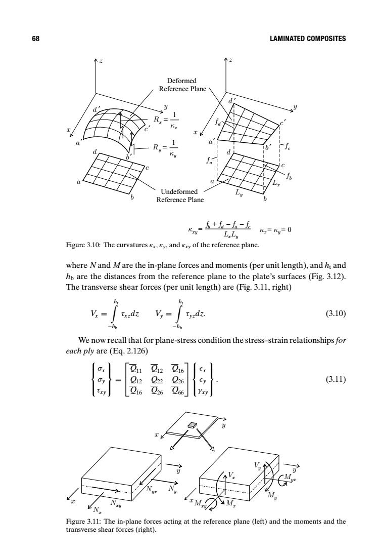
68 LAMINATED COMPOSITES 个2 个2 Deformed Reference Plane 1 R = R,= 1 Undeformed Reference Plane w=五+h-人-上 L Ly K=Kv0 Figure 3.10:The curvatures Kx.Ky,and Ky of the reference plane. where N and M are the in-plane forces and moments(per unit length),and ht and hb are the distances from the reference plane to the plate's surfaces (Fig.3.12). The transverse shear forces(per unit length)are(Fig.3.11,right) (3.10) We now recall that for plane-stress condition the stress-strain relationships for each ply are (Eq.2.126) 11 012 016 (3.11) N四 E M yM王 N Figure 3.11:The in-plane forces acting at the reference plane (left)and the moments and the transverse shear forces(right).68 LAMINATED COMPOSITES x y x y Undeformed Reference Plane c b a d c d a b Ly Lx z z Deformed Reference Plane fd fc fb fa yx cadb xy LL ffff κ + −− = κκ yx 0== b ′ b ′ a′ a′ c ′ c ′ d ′ d ′ x Rx κ 1 = y Ry κ 1 = Figure 3.10: The curvatures κx, κy, and κxy of the reference plane. where N and M are the in-plane forces and moments (per unit length), and ht and hb are the distances from the reference plane to the plate’s surfaces (Fig. 3.12). The transverse shear forces (per unit length) are (Fig. 3.11, right) Vx = ) ht −hb τxzdz Vy = ) ht −hb τyzdz. (3.10) We now recall that for plane-stress condition the stress–strain relationshipsfor each ply are (Eq. 2.126) σx σy τxy = Q11 Q12 Q16 Q12 Q22 Q26 Q16 Q26 Q66 x y γxy . (3.11) x y x y x y Nx Nxy Nyx Ny Mxy Mx My Myx Vy Vx Figure 3.11: The in-plane forces acting at the reference plane (left) and the moments and the transverse shear forces (right)