正在加载图片...
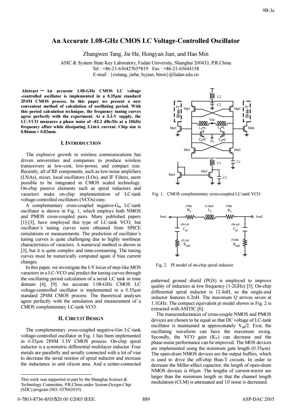
9B-3s An Accurate 1.08-GHz CMOS LC Voltage-Controlled Oscillator Zhangwen Tang,Jie He,Hongyan Jian,and Hao Min ASIC System State Key Laboratory,Fudan University,Shanghai 200433,P.R.China Tel:+86-21-65642765*819Fax:+86-21-65644158 E-mail:(zwtang,jiehe,hyjian,hmin)@fudan.edu.cn Abstract -An accurate 1.08-GHz CMOS LC voltage -controlled oscillator is implemented in a 0.35um standard 2P4M CMOS process.In this paper we present a new convenient method of calculation of oscillating period.With Mp2 this period calculation technique,the frequency tuning curves agree perfectly with the experiment.At a 3.3-V supply,the LC-VCO measures a phase noise of-82.2 dBc/Hz at a 10kHz 0Q00·一0Q00 frequency offset while dissipating 3.1mA current.Chip size is 0.86mm×0.82mm. I.INTRODUCTION Mn Mn2 The explosive growth in wireless communications has driven universities and companies to produce wireless transceivers at low-cost,low-power,and compact size. Recently,all of RF components,such as low-noise amplifiers (LNAs),mixer,local oscillators (LOs),and IF Filters.seem possible to be integrated in CMOS scaled technology. On-chip passive elements such as spiral inductors and varactors make on-chip implementation of LC-tank Fig.1. CMOS complementary cross-coupled LC-tank VCO voltage-controlled oscillators (VCOs)easy. A complementary cross-coupled negative-Gm LC-tank 5.780 1238 oscillator is shown in Fig.1,which employs both NMOS R Ls and PMOS cross-coupled pairs.Many published papers Portl O- WWQ0一WW Port2 [1]-[3],have employed this type of LC-tank VCO,but 479.5压 476.9 oscillator's tuning curves were obtained from SPICE simulations or measurements.The prediction of oscillator's tuning curves is quite challenging due to highly nonlinear 37.120 37.280 characteristics of varactors.A numerical method is shown in [3],but it is quite complex and time-consuming.The tuning curves must be numerically computed again if bias current changes. In this paper,we investigate the I-V locus of step-like MOS Fig.2.PI model of on-chip spiral inductor varactors in a LC-VCO and predict the tuning curves through the oscillating period calculation of a serial LC tank in time patterned ground shield (PGS)is employed to improve domain [4],[9].An accurate 1.08-GHz CMOS LC quality of inductors at low frequency (1-2GHz)[5].On-chip voltage-controlled oscillator is implemented in a 0.35um differential spiral inductor is 12.4nH,so the single-end standard 2P4M CMOS process.The theoretical analyses inductor features 6.2nH.The maximum Q arrives seven at agree perfectly with the simulation and measurement of a 1.1GHz.The compact equivalent pi model shown in Fig.2 is CMOS complementary LC-tank VCO. extracted with ASITIC [6]. The transconductances of cross-couple NMOS and PMOS II.CIRCUIT DESIGN devices are chosen to be equal so that DC voltage of LC-tank oscillator is maintained at approximately V2.First,the The complementary cross-coupled negative-Gm LC-tank oscillating waveform can have the maximum swing. voltage-controlled oscillator in Fig.I has been implemented Secondly,the VCO gain (Ky)can decrease and the in 0.35um 2P4M 3.3V CMOS process.On-chip spiral phase-noise performance can be improved.The MOS devices inductor is a symmetric differential multilayer inductor.Four are implemented using the minimum gate length (0.35um). metals are parallelly and serially connected with a lot of vias The open-drain NMOS devices are the output buffers,which to decrease the serial resistor of spiral inductor and increase is used to drive the off-chip Bias-T circuits.In order to the inductance in unit silicon area.And a center-connected decrease the Miller-effect capacitor,the length of open-drain NMOS devices is 60um.The lengths of current-mirror are larger than the minimum length so that the channel length This work was supported in part by the Shanghai Science modulation(CLM)is attenuated and 1/f noise is decreased. Technology Committee,P.R.China under System-Design-Chip (SDC)program (NO.037062019). 0-7803-8736-8/05/$20.00©2005IEEE. 889 ASP-DAC 2005Abstract - An accurate 1.08-GHz CMOS LC voltage -controlled oscillator is implemented in a 0.35µm standard 2P4M CMOS process. In this paper we present a new convenient method of calculation of oscillating period. With this period calculation technique, the frequency tuning curves agree perfectly with the experiment. At a 3.3-V supply, the LC-VCO measures a phase noise of –82.2 dBc/Hz at a 10kHz frequency offset while dissipating 3.1mA current. Chip size is 0.86mm× 0.82mm. I. INTRODUCTION The explosive growth in wireless communications has driven universities and companies to produce wireless transceivers at low-cost, low-power, and compact size. Recently, all of RF components, such as low-noise amplifiers (LNAs), mixer, local oscillators (LOs), and IF Filters, seem possible to be integrated in CMOS scaled technology. On-chip passive elements such as spiral inductors and varactors make on-chip implementation of LC-tank voltage-controlled oscillators (VCOs) easy. A complementary cross-coupled negative-Gm LC-tank oscillator is shown in Fig. 1, which employs both NMOS and PMOS cross-coupled pairs. Many published papers [1]-[3], have employed this type of LC-tank VCO, but oscillator’s tuning curves were obtained from SPICE simulations or measurements. The prediction of oscillator’s tuning curves is quite challenging due to highly nonlinear characteristics of varactors. A numerical method is shown in [3], but it is quite complex and time-consuming. The tuning curves must be numerically computed again if bias current changes. In this paper, we investigate the I-V locus of step-like MOS varactors in a LC-VCO and predict the tuning curves through the oscillating period calculation of a serial LC tank in time domain [4], [9]. An accurate 1.08-GHz CMOS LC voltage-controlled oscillator is implemented in a 0.35µm standard 2P4M CMOS process. The theoretical analyses agree perfectly with the simulation and measurement of a CMOS complementary LC-tank VCO. II. CIRCUIT DESIGN The complementary cross-coupled negative-Gm LC-tank voltage-controlled oscillator in Fig. 1 has been implemented in 0.35µm 2P4M 3.3V CMOS process. On-chip spiral inductor is a symmetric differential multilayer inductor. Four metals are parallelly and serially connected with a lot of vias to decrease the serial resistor of spiral inductor and increase the inductance in unit silicon area. And a center-connected This work was supported in part by the Shanghai Science & Technology Committee, P.R.China under System-Design-Chip (SDC) program (NO. 037062019). patterned ground shield (PGS) is employed to improve quality of inductors at low frequency (1-2GHz) [5]. On-chip differential spiral inductor is 12.4nH, so the single-end inductor features 6.2nH. The maximum Q arrives seven at 1.1GHz. The compact equivalent pi model shown in Fig. 2 is extracted with ASITIC [6]. The transconductances of cross-couple NMOS and PMOS devices are chosen to be equal so that DC voltage of LC-tank oscillator is maintained at approximately Vdd/2. First, the oscillating waveform can have the maximum swing. Secondly, the VCO gain (KV) can decrease and the phase-noise performance can be improved. The MOS devices are implemented using the minimum gate length (0.35µm). The open-drain NMOS devices are the output buffers, which is used to drive the off-chip Bias-T circuits. In order to decrease the Miller-effect capacitor, the length of open-drain NMOS devices is 60µm. The lengths of current-mirror are larger than the minimum length so that the channel length modulation (CLM) is attenuated and 1/f noise is decreased. An Accurate 1.08-GHz CMOS LC Voltage-Controlled Oscillator Zhangwen Tang, Jie He, Hongyan Jian, and Hao Min ASIC & System State Key Laboratory, Fudan University, Shanghai 200433, P.R.China Tel : +86-21-65642765*819 Fax : +86-21-65644158 E-mail : {zwtang, jiehe, hyjian, hmin}@fudan.edu.cn L0 =L C0=C Vc Mn1 Mn2 Mp1 Mp2 Mn5 Mn6 Mn3 Mn4 Bias-T Bias-T L1 L2 C3 C2 C1 C0=C L0=L Vdc Fig. 1. CMOS complementary cross-coupled LC-tank VCO RS LS Cp1 Cp2 Rsub1 Rsub2 RS 5.78Ω 12.38nH 5.78Ω 479.5 fF 476.9 fF 37.12Ω 37.28Ω Port1 Port2 Fig. 2. PI model of on-chip spiral inductor 889 9B-3s 0-7803-8736-8/05/$20.00 ©2005 IEEE. ASP-DAC 2005