正在加载图片...
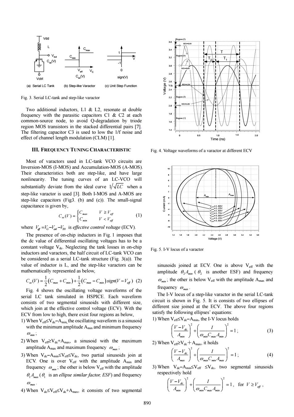
Vdd 复 C.(V) 2 Vctrl C.M sign(V) (a)Serial LC Tank (b)Step-like Varactor (c)Unit Step Function 2.4 Fig.3.Serial LC-tank and step-like varactor 23 20 Two additional inductors,LI L2,resonate at double frequency with the parasitic capacitors Cl C2 at each common-source node,to avoid Q-degradation by triode region MOS transistors in the stacked differential pairs [7]. The filtering capacitor C3 is used to low the 1/f noise and 0.5 10 effect of channel length modulation(CLM)[1]. Time(ns) III.FREQUENCY TUNING CHARACTERISTIC Fig.4.Voltage waveforms of a varactor at different ECV Most of varactors used in LC-tank VCO circuits are Inversion-MOS (I-MOS)and Accumulation-MOS (A-MOS) Their characteristics both are step-like,and have large nonlinearity.The tuning curves of an LC-VCO will substantially deviate from the ideal curve 1/LC when a step-like varactor is used [3].Both I-MOS and A-MOS are step-like capacitors (Fig3.(b)and (c)).The small-signal capacitance is given by, V≥' C(V)= (1) V<V .50 where V=V-Vin-Vi is effective control voltage (ECV). The presence of on-chip inductors in Fig.I imposes that 1.4 22 1428 25 the dc value of differential oscillating voltages has to be a Voltage(V) constant voltage Vae.Neglecting the tank losses in on-chip Fig.5.I-V locus of a varactor inductors and varactors,the half circuit of LC-tank VCO can be considered as a serial LC-tank structure (Fig.3(a)).The value of inductor is L,and the step-like varactors can be sinusoids joined at ECV.One is above Ver with the mathematically represented as below, amplitude 4(is another ESF)and frequency C.W)-(C+C)+(C-C)ign-V)) the other is below Ver with the amplitude Amx and Fig.4 shows the oscillating voltage waveforms of the frequency mr serial LC tank simulated in HSPICE.Each waveform The I-V locus of a step-like varactor in the serial LC-tank consists of two segmental sinusoids with different size circuit is shown in Fig.5.It is consists of two ellipses of which join at the effective control voltage (ECV).With the different size joined at the ECV.The above four regions ECV from low to high,there exist four regions as below, satisfy the following ellipses'equations: 1)When VensVde-Amin,the oscillating waveform is a sinusoid 1)When VensVde-Amin,the I-V locus holds with the minimum amplitude Amin and minimum frequency =1 @ain 、Am (3) 2)When Ven2Vde+Amax,a sinusoid with the maximum 2)When VenVde+Amax,it holds amplitude Amax and maximum frequency; 2 3)When Vde-AminsVensVdc,two partial sinusoids join at V-Vk =1 (4) ECV.One is over Verr with the amplitude Amin and A frequency the other is below Ve with the amplitude 3)When Vde-AminsVerr sVdc,two segmental sinusoids 6 A(is an ellipse similar factor.ESF)and frequency respectively hold 包s =1,forV≥'g 4)When VdesVensVde+Amax,it consists of two segmental 890Two additional inductors, L1 & L2, resonate at double frequency with the parasitic capacitors C1 & C2 at each common-source node, to avoid Q-degradation by triode region MOS transistors in the stacked differential pairs [7]. The filtering capacitor C3 is used to low the 1/f noise and effect of channel length modulation (CLM) [1]. III. FREQUENCY TUNING CHARACTERISTIC Most of varactors used in LC-tank VCO circuits are Inversion-MOS (I-MOS) and Accumulation-MOS (A-MOS). Their characteristics both are step-like, and have large nonlinearity. The tuning curves of an LC-VCO will substantially deviate from the ideal curve 1 LC when a step-like varactor is used [3]. Both I-MOS and A-MOS are step-like capacitors (Fig3. (b) and (c)). The small-signal capacitance is given by, ( ) max eff ss min eff C VV C V C VV ⎧⎪ ≥ = ⎨ ⎪ < ⎩ (1) where V VV V eff G ctrl TH =− − is effective control voltage (ECV). The presence of on-chip inductors in Fig. 1 imposes that the dc value of differential oscillating voltages has to be a constant voltage Vdc. Neglecting the tank losses in on-chip inductors and varactors, the half circuit of LC-tank VCO can be considered as a serial LC-tank structure (Fig. 3(a)). The value of inductor is L, and the step-like varactors can be mathematically represented as below, ( ) ( ) 1 1 () ( ) 2 2 C V C C C C sign V V ss max min max min eff = ++ − − (2) Fig. 4 shows the oscillating voltage waveforms of the serial LC tank simulated in HSPICE. Each waveform consists of two segmental sinusoids with different size, which join at the effective control voltage (ECV). With the ECV from low to high, there exist four regions as below, 1) When Veff≤Vdc−Amin, the oscillating waveform is a sinusoid with the minimum amplitude Amin and minimum frequency ω min ; 2) When Veff≥Vdc+Amax, a sinusoid with the maximum amplitude Amax and maximum frequency ω max ; 3) When Vdc−Amin≤Veff≤Vdc, two partial sinusoids join at ECV. One is over Veff with the amplitude Amin and frequency ω min ; the other is below Veff with the amplitude θ1Amax (θ1 is an ellipse similar factor, ESF) and frequency ω max . 4) When Vdc≤Veff≤Vdc+Amax, it consists of two segmental sinusoids joined at ECV. One is above Veff with the amplitude θ 2Amin ( θ 2 is another ESF) and frequency ω min ; the other is below Veff with the amplitude Amax and frequency ω max . The I-V locus of a step-like varactor in the serial LC-tank circuit is shown in Fig. 5. It is consists of two ellipses of different size joined at the ECV. The above four regions satisfy the following ellipses’ equations: 1) When Veff≤Vdc−Amin, the I-V locus holds 2 2 1 ω ⎛ ⎞⎛ ⎞ − ⎜ ⎟⎜ ⎟ + = ⎝ ⎠⎝ ⎠ dc min min max min V V I A CA ; (3) 2) When Veff≥Vdc+Amax, it holds 2 2 1 ω ⎛ ⎞⎛ ⎞ − ⎜ ⎟⎜ ⎟ + = ⎝ ⎠⎝ ⎠ dc max max min max V V I A CA ; (4) 3) When Vdc−Amin≤Veff ≤Vdc, two segmental sinusoids respectively hold 2 2 1 ω ⎛ ⎞⎛ ⎞ − ⎜ ⎟⎜ ⎟ + = ⎝ ⎠⎝ ⎠ dc min min max min V V I A CA , for V V≥ eff , L Css(V) Vdd Vctrl Cmax Cmin Veff VC 1 -1 0 V Css(V) sign(V) (a) Serial LC Tank (b) Step-like Varactor (c) Unit Step Function Vout Fig. 3. Serial LC-tank and step-like varactor 3.6 3.4 3.2 3.0 2.8 2.6 2.2 2.0 1.8 2.4 1.6 1.4 Voltage (V) 0 0.5 1.0 1.5 2.0 Time (ns) T1 T2 T Vdc ECV=3.5V ECV=3.0V ECV=2.5V ECV=2.0V Region (1) Region (2) Region (3) Region (4) Fig. 4. Voltage waveforms of a varactor at different ECV Amin Amax V eff =2.00V V eff =2.25V V eff =2.50V V eff =2.75V V eff =3.00V V eff =3.25V V eff =3.50V 1.4 1.6 1.8 2.0 2.2 2.4 2.6 2.8 3.0 3.2 3.4 3.6 10 8 6 4 2 0 -4 -6 -8 -2 -10 Current (mA) Voltage (V) Fig. 5. I-V locus of a varactor 890