正在加载图片...
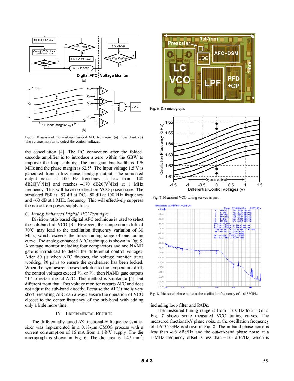
Digital AFC start 47mm 8”Comp7 Wait 80us N FC+DSM Shift VCO band N AFC finished Digital AFC:Voltage Monitor (a) AFC Fig.6.Die micrograph VLinear Range (AV 1.66 ch (b) A工O 1.65 Fig.5.Diagram of the analog-enhanced AFC technique.(a)Flow chart.(b) The voltage monitor to detect the control voltages. 1.64 the cancellation [4].The RC connection after the folded- 1.63 cascode amplifier is to introduce a zero within the GBW to improve the loop stability.The unit-gain bandwidth is 176 MHz and the phase margin is 62.5.The input voltage 1.5 V is 1.62 generated from a low noise bandgap output.The simulated 8 ""m output noise at 100 Hz frequency is less than -140 1.61 一Symmetrica dB20[V2/Hz]and reaches -170 dB20[V2/Hz]at 1 MHz -1.5 -0.50 0.5 1.5 frequency.This will have no effect on VCO phase noise.The Differential Control Voltages (V) simulated PSR is-97 dB at DC,-80 dB at 100 kHz frequency and-60 dB at 1 MHz frequency.This will effectively suppress Fig.7.Measured VCO tuning curves in part. the noise from power supply lines. Ph/Raf-d 0.0 C.Analog-Enhanced Digital AFC Technique 0的 Division-ratio-based digital AFC technique is used to select 0的 48.5313小 the sub-band of VCO [3].However,the temperature drift of . 70C may lead to the oscillation frequency variation of 30 0.的 MHz,which exceeds the linear tuning range of one tuning 0.的 0国 curve.The analog-enhanced AFC technique is shown in Fig.5. 前的 A voltage monitor including four comparators and one NAND 第.国 gate is introduced to detect the differential control voltages 1000 After 80 us when AFC finishes,the voltage monitor starts 1100 working.80 us is to ensure the synthesizer has been locked. 20月 When the synthesizer looses lock due to the temperature drift, 300 the control voltages exceed Veh or Vel,then NAND gate outputs 1400 "1"to restart digital AFC.This method is similar to [5],but 150.0 1600 different from that.This voltage monitor restarts AFC and does not adjust the sub-band directly.Because the AFC time is very 70 short,restarting AFC can always ensure the operation of VCO Fig.8.Measured phase noise at the oscillation frequency of 1.6135GHz. closest to the center frequency of the sub-band with adding only a little more time including loop filter and PADs IV.EXPERIMENTAL RESULTS The measured tuning range is from 1.2 GHz to 2.1 GHz. Fig.7 shows some measured VCO tuning curves.The The differentially-tuned AE fractional-N frequency synthe- measured fractional-N phase noise at the oscillation frequency sizer was implemented in a 0.18-um CMOS process with a of 1.6135 GHz is shown in Fig.8.The in-band phase noise is current consumption of 16 mA from a 1.8-V supply.The die less than -96 dBc/Hz and the out-of-band phase noise at a micrograph is shown in Fig.6.The die area is 1.47 mm2, 1-MHz frequency offset is less than-123 dBc/Hz,which is 5-4-3 55the cancellation [4]. The RC connection after the foldedcascode amplifier is to introduce a zero within the GBW to improve the loop stability. The unit-gain bandwidth is 176 MHz and the phase margin is 62.5°. The input voltage 1.5 V is generated from a low noise bandgap output. The simulated output noise at 100 Hz frequency is less than –140 dB20[V2 /Hz] and reaches –170 dB20[V2 /Hz] at 1 MHz frequency. This will have no effect on VCO phase noise. The simulated PSR is –97 dB at DC, –80 dB at 100 kHz frequency and –60 dB at 1 MHz frequency. This will effectively suppress the noise from power supply lines. C. Analog-Enhanced Digital AFC Technique Division-ratio-based digital AFC technique is used to select the sub-band of VCO [3]. However, the temperature drift of 70℃ may lead to the oscillation frequency variation of 30 MHz, which exceeds the linear tuning range of one tuning curve. The analog-enhanced AFC technique is shown in Fig. 5. A voltage monitor including four comparators and one NAND gate is introduced to detect the differential control voltages. After 80 μs when AFC finishes, the voltage monitor starts working. 80 μs is to ensure the synthesizer has been locked. When the synthesizer looses lock due to the temperature drift, the control voltages exceed Vch or Vcl, then NAND gate outputs “1” to restart digital AFC. This method is similar to [5], but different from that. This voltage monitor restarts AFC and does not adjust the sub-band directly. Because the AFC time is very short, restarting AFC can always ensure the operation of VCO closest to the center frequency of the sub-band with adding only a little more time. IV. EXPERIMENTAL RESULTS The differentially-tuned ΔΣ fractional-N frequency synthesizer was implemented in a 0.18-μm CMOS process with a current consumption of 16 mA from a 1.8-V supply. The die micrograph is shown in Fig. 6. The die area is 1.47 mm2 , including loop filter and PADs. The measured tuning range is from 1.2 GHz to 2.1 GHz. Fig. 7 shows some measured VCO tuning curves. The measured fractional-N phase noise at the oscillation frequency of 1.6135 GHz is shown in Fig. 8. The in-band phase noise is less than –96 dBc/Hz and the out-of-band phase noise at a 1-MHz frequency offset is less than –123 dBc/Hz, which is (a) (b) Fig. 5. Diagram of the analog-enhanced AFC technique. (a) Flow chart. (b) The voltage monitor to detect the control voltages. 1mm Fig. 6. Die micrograph. Fig. 8. Measured phase noise at the oscillation frequency of 1.6135GHz. -1.5 -1 -0.5 0 0.5 1 1.5 1.61 1.62 1.63 1.64 1.65 1.66 Differential Control Voltages (V) Oscillation Frequency (GHz) Fig. 7. Measured VCO tuning curves in part. 5-4-3 55