正在加载图片...
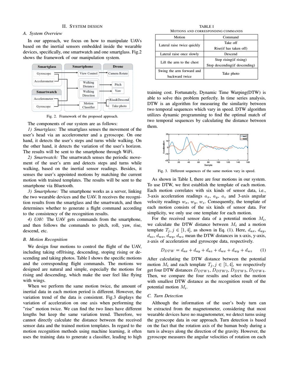
II.SYSTEM DESIGN TABLE I A.System Overview MOTIONS AND CORRESPONDING COMMANDS Motion Command In our approach,we focus on how to manipulate UAVs Take off based on the inertial sensors embedded inside the wearable Lateral raise twice quickly Rise(if has taken off) devices,specifically,one smartwatch and one smartglass.Fig.2 Lateral raise once slowly Descend shows the framework of our manipulation system. Stop rising(if rising) Lift the arm to the chest Smartglass Smartphone Drone Stop descending(if descending) Swing the arm forward and Gyroscope View Control Camera Rotate Take photo backward twice Accelerometer Walking Distance Pitch Smartwatch Walking Yaw training cost.Fortunately,Dynamic Time Warping(DTW)is Direction Rise&Descend able to solve this problem perfectly.In time series analysis, Motion Gyroscope Take photo DTW is an algorithm for measuring the similarity between Classifier two temporal sequences which vary in speed.DTW algorithm Fig.2.Framework of the proposed approach. utilizes dynamic programming to find the optimal match of The components of our system are as follows: two temporal sequences by calculating the distance between them. 1)Smartglass:The smartglass senses the movement of the user's head via an accelerometer and a gyroscope.On one hand,it detects the user's steps and turns while walking.On the other hand,it detects the variation of the user's horizon. The results will be sent to the smartphone through WiFi. 2)Smartwatch:The smartwatch senses the periodic move- ment of the user's arm and detects steps and turns while 80 100 120 140 Sample walking,based on the inertial sensor readings.Besides,it Fig.3.Different sequences of the same motion vary in speed. senses the user's appointed motions by matching the current motion with trained templates.The results will be sent to the As shown in Table I,there are four motions in our system. smartphone via Bluetooth. To use DTW,we first establish the template of each motion. 3)Smartphone:The smartphone works as a server,linking Each motion correlates with six kinds of sensor data,i.e., the two wearable devices and the UAV.It receives the recogni- 3-axis acceleration readings ar,ay,a and 3-axis angular tion results from the smartglass and the smartwatch,and then velocity readings wz,wy,w.Consequently,the template of determines whether to generate a flight command according each motion consists of the six kinds of sensor data.For to the consistency of the recognition results. simplicity,we only use one template for each motion. 4)UAV:The UAV gets commands from the smartphone, For the received sensor data of a potential motion Mi, and then follows the commands to pitch,roll,yaw,rise, we calculate the DTW distance between Mi and a motion descend,etc. template Ti,j[1,4],as shown in Eq.(1).Here,daz,day, daz,dwz,dwy,d mean the DTW distances in x-axis,y-axis, B.Motion Recognition z-axis of acceleration and gyroscope data,respectively. We design four motions to control the flight of the UAV. including taking off/rising,descending,stoping rising or de- DDTW dar day+daz dwz+dwy dwz (1) scending and taking photos.Table I shows the specific motions After calculating the DTW distance between the potential and the corresponding flight commands.The motions we motion Mi and each template Ti,j [1,4],we respectively designed are natural and simple,especially the motions for get four DTW distances DDTw1,DpTw2,DDTw3.DDTw4. rising and descending,which make the user feel like flying Then,we compare the four results and select the motion with wings. with smallest DTW distance as the recognition result of the When we perform the same motion twice,the amount of potential motion Mi inertial data in each motion period is different.However,the variation trend of the data is consistent.Fig.3 displays the C.Turn Detection variation of acceleration on one axis when performing the Although the information of the user's body turn can "rise"motion twice.We can find the two lines have different be extracted from the magnetometer,considering that most lengths but keep the same variation trend.Therefore,we wearable devices have no magnetometer,we detect turns using cannot directly calculate the distance between the received the gyroscope data in our approach.Turn detection is based sensor data and the trained motion templates.In regard to the on the fact that the rotation axis of the human body during a motion recognition methods using machine learning,it often turn is always along the direction of the gravity.However,the uses the training data to generate a classifier,leading to high gyroscope measures the angular velocities of rotation on eachII. SYSTEM DESIGN A. System Overview In our approach, we focus on how to manipulate UAVs based on the inertial sensors embedded inside the wearable devices, specifically, one smartwatch and one smartglass. Fig.2 shows the framework of our manipulation system. Fig. 2. Framework of the proposed approach. The components of our system are as follows: 1) Smartglass: The smartglass senses the movement of the user’s head via an accelerometer and a gyroscope. On one hand, it detects the user’s steps and turns while walking. On the other hand, it detects the variation of the user’s horizon. The results will be sent to the smartphone through WiFi. 2) Smartwatch: The smartwatch senses the periodic movement of the user’s arm and detects steps and turns while walking, based on the inertial sensor readings. Besides, it senses the user’s appointed motions by matching the current motion with trained templates. The results will be sent to the smartphone via Bluetooth. 3) Smartphone: The smartphone works as a server, linking the two wearable devices and the UAV. It receives the recognition results from the smartglass and the smartwatch, and then determines whether to generate a flight command according to the consistency of the recognition results. 4) UAV: The UAV gets commands from the smartphone, and then follows the commands to pitch, roll, yaw, rise, descend, etc. B. Motion Recognition We design four motions to control the flight of the UAV, including taking off/rising, descending, stoping rising or descending and taking photos. Table I shows the specific motions and the corresponding flight commands. The motions we designed are natural and simple, especially the motions for rising and descending, which make the user feel like flying with wings. When we perform the same motion twice, the amount of inertial data in each motion period is different. However, the variation trend of the data is consistent. Fig.3 displays the variation of acceleration on one axis when performing the ”rise” motion twice. We can find the two lines have different lengths but keep the same variation trend. Therefore, we cannot directly calculate the distance between the received sensor data and the trained motion templates. In regard to the motion recognition methods using machine learning, it often uses the training data to generate a classifier, leading to high TABLE I MOTIONS AND CORRESPONDING COMMANDS Motion Command Lateral raise twice quickly Take off Rise(if has taken off) Lateral raise once slowly Descend Lift the arm to the chest Stop rising(if rising) Stop descending(if descending) Swing the arm forward and Take photo backward twice training cost. Fortunately, Dynamic Time Warping(DTW) is able to solve this problem perfectly. In time series analysis, DTW is an algorithm for measuring the similarity between two temporal sequences which vary in speed. DTW algorithm utilizes dynamic programming to find the optimal match of two temporal sequences by calculating the distance between them. Sample 0 20 40 60 80 100 120 140 160 Acceleration -20 -10 0 10 20 test1 test2 Fig. 3. Different sequences of the same motion vary in speed. As shown in Table I, there are four motions in our system. To use DTW, we first establish the template of each motion. Each motion correlates with six kinds of sensor data, i.e., 3-axis acceleration readings 𝑎𝑥, 𝑎𝑦, 𝑎𝑧 and 3-axis angular velocity readings 𝑤𝑥, 𝑤𝑦, 𝑤𝑧. Consequently, the template of each motion consists of the six kinds of sensor data. For simplicity, we only use one template for each motion. For the received sensor data of a potential motion 𝑀𝑖, we calculate the DTW distance between 𝑀𝑖 and a motion template 𝑇𝑗 , 𝑗 ∈ [1, 4], as shown in Eq. (1). Here, 𝑑𝑎𝑥, 𝑑𝑎𝑦, 𝑑𝑎𝑧, 𝑑𝑤𝑥, 𝑑𝑤𝑦, 𝑑𝑤𝑧 mean the DTW distances in x-axis, y-axis, z-axis of acceleration and gyroscope data, respectively. 𝐷𝐷𝑇𝑊 = 𝑑𝑎𝑥 + 𝑑𝑎𝑦 + 𝑑𝑎𝑧 + 𝑑𝑤𝑥 + 𝑑𝑤𝑦 + 𝑑𝑤𝑧 (1) After calculating the DTW distance between the potential motion 𝑀𝑖 and each template 𝑇𝑗 , 𝑗 ∈ [1, 4], we respectively get four DTW distances 𝐷𝐷𝑇𝑊1, 𝐷𝐷𝑇𝑊2, 𝐷𝐷𝑇𝑊3, 𝐷𝐷𝑇𝑊4. Then, we compare the four results and select the motion with smallest DTW distance as the recognition result of the potential motion 𝑀𝑖. C. Turn Detection Although the information of the user’s body turn can be extracted from the magnetometer, considering that most wearable devices have no magnetometer, we detect turns using the gyroscope data in our approach. Turn detection is based on the fact that the rotation axis of the human body during a turn is always along the direction of the gravity. However, the gyroscope measures the angular velocities of rotation on each