正在加载图片...

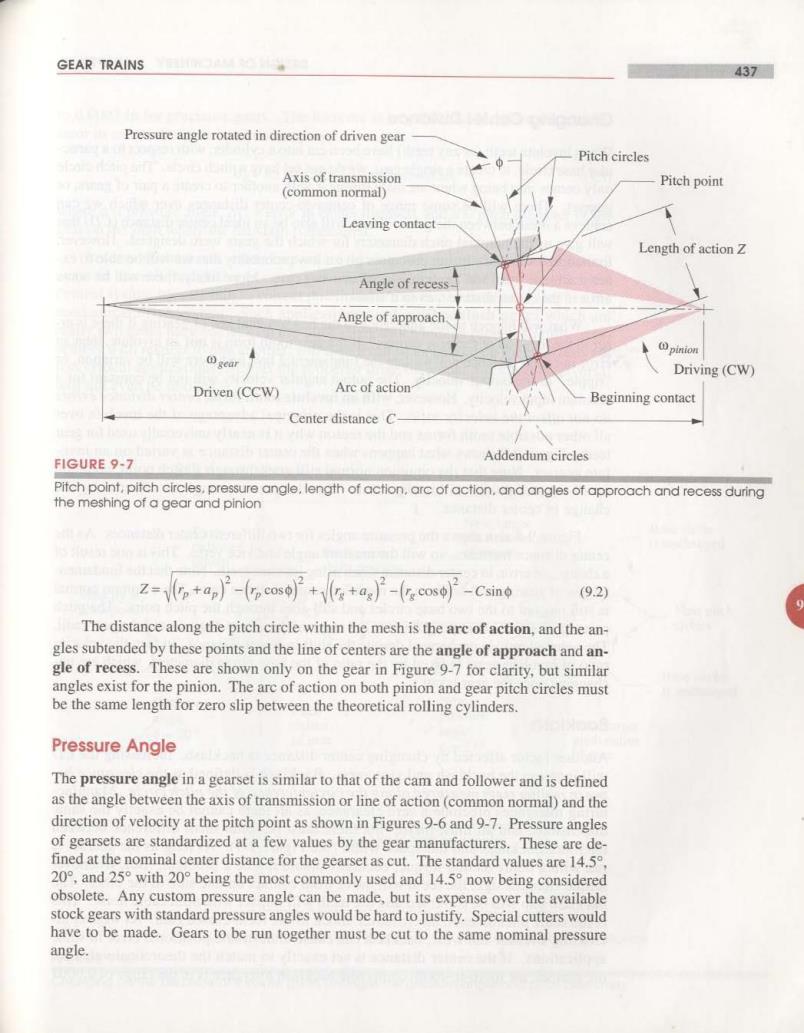
GEAR TRAINS 437 Pressure angle rotated in direction of driven gear Pitch circles Axis of transmission Pitch point (common normal) Leaving contact Length of action Z Angle of recess Angle of approach. gear pinion Driving(CW) Driven(CCW) Arc of action Beginning contact Center distance C- FIGURE 9-7 Addendum circles Pitch point,pitch circles,pressure angle,length of action.arc of action.and angles of approach and recess during the meshing of a gear and pinion z-p+ap)-(c)++a)-(cos)-csino (92) The distance along the pitch circle within the mesh is the are of action,and the an- gles subtended by these points and the line of centers are the angle of approach and an- gle of recess.These are shown only on the gear in Figure 9-7 for clarity,but similar angles exist for the pinion.The arc of action on both pinion and gear pitch circles must be the same length for zero slip between the theoretical rolling cylinders. Pressure Angle The pressure angle in a gearset is similar to that of the cam and follower and is defined as the angle between the axis of transmission or line of action(common normal)and the direction of velocity at the pitch point as shown in Figures 9-6 and 9-7.Pressure angles of gearsets are standardized at a few values by the gear manufacturers.These are de- fined at the nominal center distance for the gearset as cut.The standard values are 14.5, 20°,and25°with20°being the most commonly used and 14.5°now being considered obsolete.Any custom pressure angle can be made,but its expense over the available stock gears with standard pressure angles would be hard to justify.Special cutters would have to be made.Gears to be run together must be cut to the same nominal pressure angle