正在加载图片...

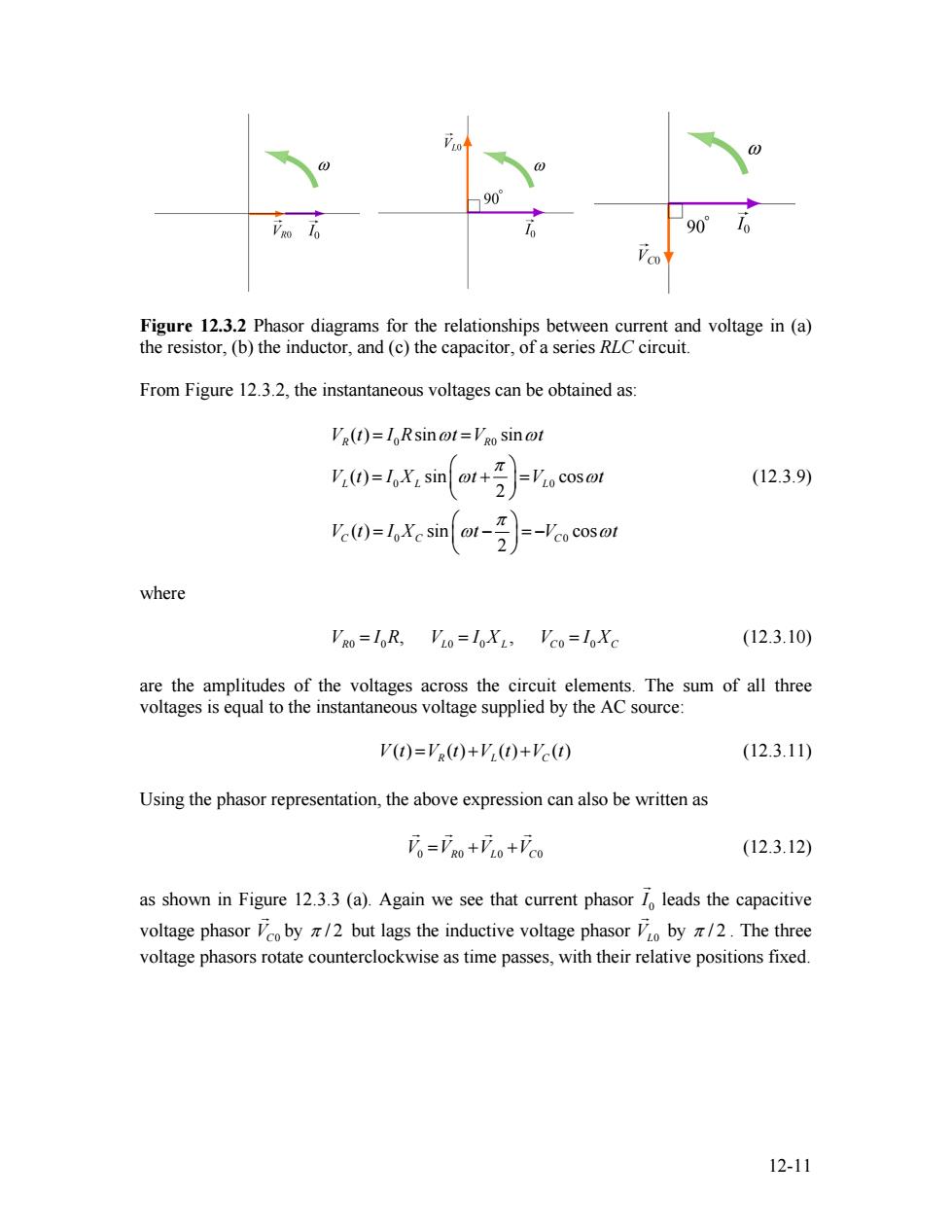
e 90 10 90 Figure 12.3.2 Phasor diagrams for the relationships between current and voltage in (a) the resistor,(b)the inductor,and(c)the capacitor,of a series RLC circuit. From Figure 12.3.2,the instantaneous voltages can be obtained as: Vg(t)=IoRsin @t=Vgo sin @t V()=1X:sint+ (12.3.9) 2 V()sinr- -Vco cos@t where VRO=I0R,VLo=I0X1>VCo=l0Xc (12.3.10) are the amplitudes of the voltages across the circuit elements.The sum of all three voltages is equal to the instantaneous voltage supplied by the AC source: V(t)=VR(t)+V(t)+Vc(t) (12.3.11) Using the phasor representation,the above expression can also be written as Fo=FRo+VLo+VCo (12.3.12) as shown in Figure 12.3.3(a).Again we see that current phasor 1 leads the capacitive voltage phasor oby /2 but lags the inductive voltage phasor o by /2.The three voltage phasors rotate counterclockwise as time passes,with their relative positions fixed. 12-11Figure 12.3.2 Phasor diagrams for the relationships between current and voltage in (a) the resistor, (b) the inductor, and (c) the capacitor, of a series RLC circuit. From Figure 12.3.2, the instantaneous voltages can be obtained as: 0 0 0 0 0 0 ( ) sin sin ( ) sin cos 2 ( ) sin cos 2 R R L L L C C C V t I R t V t V t I X t V t V t I X t V t ω ω π ω π ω ω ω = = ⎛ ⎞ = + ⎜ ⎟ = ⎝ ⎠ ⎛ ⎞ = − ⎜ ⎟ = − ⎝ ⎠ (12.3.9) where (12.3.10) 0 0 0 0 0 0 , , V I R L R V L C = = I X V = I XC are the amplitudes of the voltages across the circuit elements. The sum of all three voltages is equal to the instantaneous voltage supplied by the AC source: ( ) ( ) ( ) ( ) V t VR L C = t + + V t V t (12.3.11) Using the phasor representation, the above expression can also be written as V V 0 0 = + R L V 0 +VC0 G G G G (12.3.12) as shown in Figure 12.3.3 (a). Again we see that current phasor 0 I G leads the capacitive voltage phasor by VC0 G π / 2 but lags the inductive voltage phasor VL0 G by π / 2 . The three voltage phasors rotate counterclockwise as time passes, with their relative positions fixed. 12-11