正在加载图片...

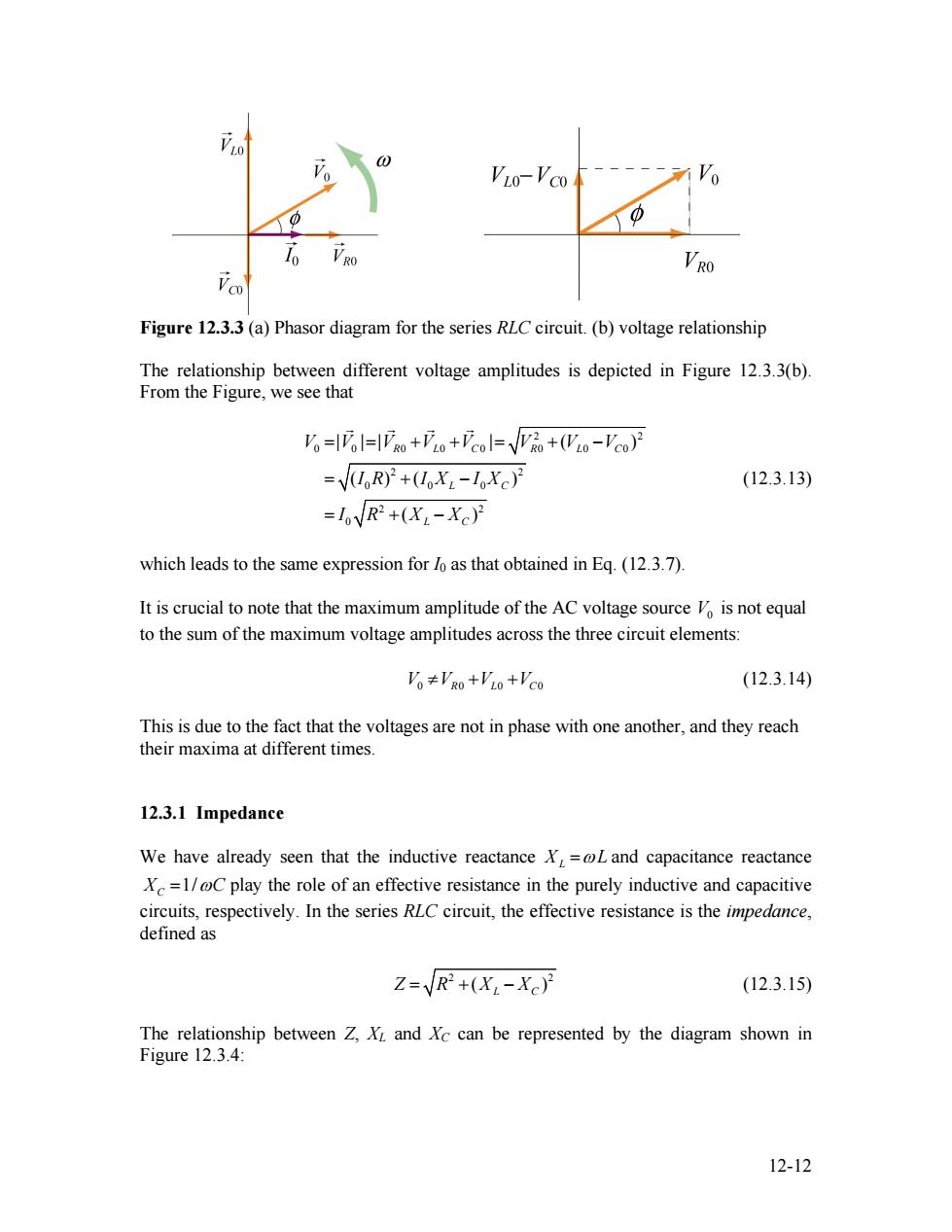
LO VLO-Vco Vo 10 VRO Figure 12.3.3 (a)Phasor diagram for the series RLC circuit.(b)voltage relationship The relationship between different voltage amplitudes is depicted in Figure 12.3.3(b). From the Figure,we see that 。=l=o+o+col=Vo+(Wo-'co月 =VR)2+(X2-1Xc)2 (12.3.13) =loVR2+(XL-Xc) which leads to the same expression for lo as that obtained in Eq.(12.3.7) It is crucial to note that the maximum amplitude of the AC voltage source is not equal to the sum of the maximum voltage amplitudes across the three circuit elements: V。≠VRo+'o+'co (12.3.14) This is due to the fact that the voltages are not in phase with one another,and they reach their maxima at different times. 12.3.1 Impedance We have already seen that the inductive reactance X,=oL and capacitance reactance X=1/@C play the role of an effective resistance in the purely inductive and capacitive circuits,respectively.In the series RLC circuit,the effective resistance is the impedance, defined as Z=/R2+(X:-Xc) (12.3.15) The relationship between Z,XL and Xc can be represented by the diagram shown in Figure 12.3.4: 12-12Figure 12.3.3 (a) Phasor diagram for the series RLC circuit. (b) voltage relationship The relationship between different voltage amplitudes is depicted in Figure 12.3.3(b). From the Figure, we see that 2 2 0 0 0 0 0 0 0 0 2 2 0 0 0 2 2 0 | | | | ( ) ( ) ( ) ( ) R L C R L C L C L C V V V V V V V V I R I X I X I R X X = = + + = + − = + − = + − G G G G (12.3.13) which leads to the same expression for I0 as that obtained in Eq. (12.3.7). It is crucial to note that the maximum amplitude of the AC voltage source is not equal to the sum of the maximum voltage amplitudes across the three circuit elements: V0 V V 0 0 ≠ R L + + V 0 VC0 (12.3.14) This is due to the fact that the voltages are not in phase with one another, and they reach their maxima at different times. 12.3.1 Impedance We have already seen that the inductive reactance XL =ωL and capacitance reactance 1/ XC = ωC play the role of an effective resistance in the purely inductive and capacitive circuits, respectively. In the series RLC circuit, the effective resistance is the impedance, defined as 2 ( Z R = + XL − XC 2 ) (12.3.15) The relationship between Z, XL and XC can be represented by the diagram shown in Figure 12.3.4: 12-12