正在加载图片...

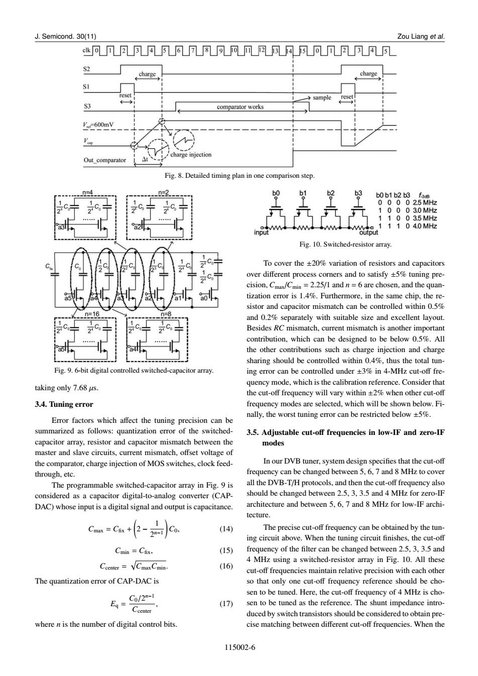
J.Semicond.30(11) Zou Liang et al. k可ΠA凡678可网风风34可凡2A凡 S2 charge charge SI sample reset S3 comparator works -600mV Ve charge injection Out comparator Fig.8.Detailed timing plan in one comparison step. n=4 _n=2. b1 b2 b3 b0 b1 b2 b3 fo 000025MHz 10003.0MHz 11003.5MHz 11104.0MHz Fig.10.Switched-resistor array. To cover the +20%variation of resistors and capacitors over different process corners and to satisfy +5%tuning pre- cision,Cmax/Cmin =2.25/1 and n=6 are chosen,and the quan- tization error is 1.4%.Furthermore,in the same chip,the re- sistor and capacitor mismatch can be controlled within 0.5% n=16 and 0.2%separately with suitable size and excellent layout. Besides RC mismatch,current mismatch is another important contribution,which can be designed to be below 0.5%.All the other contributions such as charge injection and charge sharing should be controlled within 0.4%,thus the total tun- Fig.9.6-bit digital controlled switched-capacitor array. ing error can be controlled under +3%in 4-MHz cut-off fre- taking only 7.68 us. quency mode,which is the calibration reference.Consider that the cut-off frequency will vary within +2%when other cut-off 3.4.Tuning error frequency modes are selected,which will be shown below.Fi- nally,the worst tuning error can be restricted below +5%. Error factors which affect the tuning precision can be summarized as follows:quantization error of the switched- 3.5.Adjustable cut-off frequencies in low-IF and zero-IF capacitor array,resistor and capacitor mismatch between the modes master and slave circuits,current mismatch,offset voltage of the comparator,charge injection of MOS switches,clock feed- In our DVB tuner,system design specifies that the cut-off through,etc. frequency can be changed between 5,6.7 and 8 MHz to cover The programmable switched-capacitor array in Fig.9 is all the DVB-T/H protocols,and then the cut-off frequency also considered as a capacitor digital-to-analog converter(CAP- should be changed between 2.5,3,3.5 and 4 MHz for zero-IF DAC)whose input is a digital signal and output is capacitance. architecture and between 5,6,7 and 8 MHz for low-IF archi- tecture. -Ca+2-)Co. (14) The precise cut-off frequency can be obtained by the tun- ing circuit above.When the tuning circuit finishes,the cut-off Cmin =Cfx, (15) frequency of the filter can be changed between 2.5,3,3.5 and 4 MHz using a switched-resistor array in Fig.10.All these Ccenter =VCmax Cmin (16) cut-off frequencies maintain relative precision with each other The quantization error of CAP-DAC is so that only one cut-off frequency reference should be cho- _Co/2-1 sen to be tuned.Here,the cut-off frequency of 4 MHz is cho- Eg二Ccenter (17) sen to be tuned as the reference.The shunt impedance intro- duced by switch transistors should be considered to obtain pre- where n is the number of digital control bits. cise matching between different cut-off frequencies.When the 115002-6J. Semicond. 30(11) Zou Liang et al. Fig. 8. Detailed timing plan in one comparison step. Fig. 9. 6-bit digital controlled switched-capacitor array. taking only 7.68 µs. 3.4. Tuning error Error factors which affect the tuning precision can be summarized as follows: quantization error of the switchedcapacitor array, resistor and capacitor mismatch between the master and slave circuits, current mismatch, offset voltage of the comparator, charge injection of MOS switches, clock feedthrough, etc. The programmable switched-capacitor array in Fig. 9 is considered as a capacitor digital-to-analog converter (CAPDAC) whose input is a digital signal and output is capacitance. Cmax = Cfix + ( 2 − 1 2 n−1 ) C0, (14) Cmin = Cfix, (15) Ccenter = √ CmaxCmin. (16) The quantization error of CAP-DAC is Eq = C0/2 n−1 Ccenter , (17) where n is the number of digital control bits. Fig. 10. Switched-resistor array. To cover the ±20% variation of resistors and capacitors over different process corners and to satisfy ±5% tuning precision, Cmax/Cmin = 2.25/1 and n = 6 are chosen, and the quantization error is 1.4%. Furthermore, in the same chip, the resistor and capacitor mismatch can be controlled within 0.5% and 0.2% separately with suitable size and excellent layout. Besides RC mismatch, current mismatch is another important contribution, which can be designed to be below 0.5%. All the other contributions such as charge injection and charge sharing should be controlled within 0.4%, thus the total tuning error can be controlled under ±3% in 4-MHz cut-off frequency mode, which is the calibration reference. Consider that the cut-off frequency will vary within ±2% when other cut-off frequency modes are selected, which will be shown below. Finally, the worst tuning error can be restricted below ±5%. 3.5. Adjustable cut-off frequencies in low-IF and zero-IF modes In our DVB tuner, system design specifies that the cut-off frequency can be changed between 5, 6, 7 and 8 MHz to cover all the DVB-T/H protocols, and then the cut-off frequency also should be changed between 2.5, 3, 3.5 and 4 MHz for zero-IF architecture and between 5, 6, 7 and 8 MHz for low-IF architecture. The precise cut-off frequency can be obtained by the tuning circuit above. When the tuning circuit finishes, the cut-off frequency of the filter can be changed between 2.5, 3, 3.5 and 4 MHz using a switched-resistor array in Fig. 10. All these cut-off frequencies maintain relative precision with each other so that only one cut-off frequency reference should be chosen to be tuned. Here, the cut-off frequency of 4 MHz is chosen to be tuned as the reference. The shunt impedance introduced by switch transistors should be considered to obtain precise matching between different cut-off frequencies. When the 115002-6