正在加载图片...
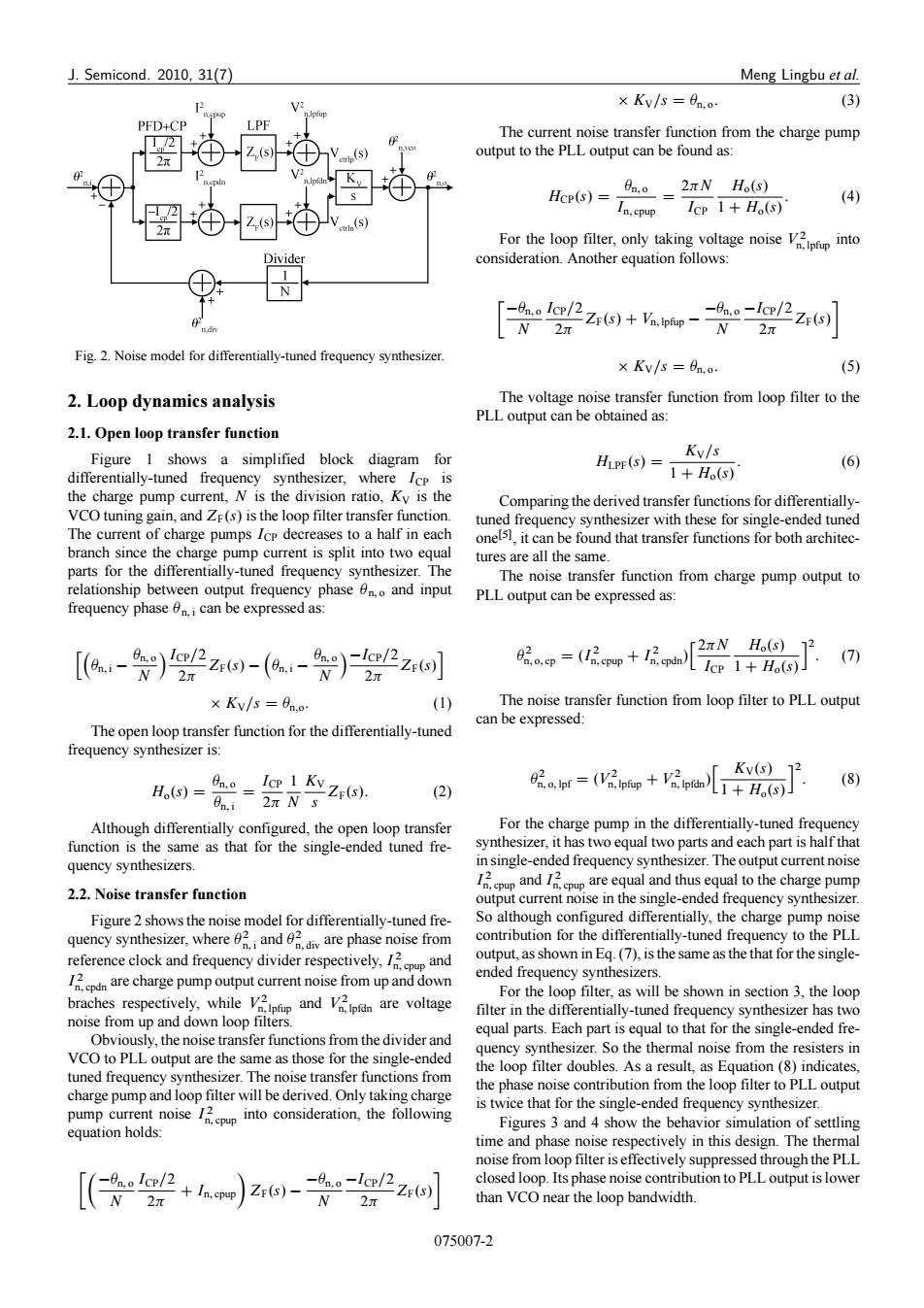
J.Semicond.2010,31(7) Meng Lingbu et al. ×Kv/s=fn.o (3) PFD+CP The current noise transfer function from the charge pump output to the PLL output can be found as: Hcp(s)=- a。=2πN(0) (4) In,cpup Icp 1+Ho(s) For the loop filter,only taking voltage noise into Divide consideration.Another equation follows: -4ao-lc/2z6)】 -0n.Ice/2Z(s)+Vn.Ipiup N 27 2π Fig.2.Noise model for differentially-tuned frequency synthesizer ×Kv/s=9n.o (5) 2.Loop dynamics analysis The voltage noise transfer function from loop filter to the PLL output can be obtained as: 2.1.Open loop transfer function Figure 1 shows a simplified block diagram for Kv/s differentially-tuned frequency synthesizer,where Icp is He(⊙)=1+HoS (6) the charge pump current,N is the division ratio,Ky is the Comparing the derived transfer functions for differentially- VCO tuning gain,and ZF(s)is the loop filter transfer function. tuned frequency synthesizer with these for single-ended tuned The current of charge pumps Icp decreases to a half in each one[5],it can be found that transfer functions for both architec- branch since the charge pump current is split into two equal tures are all the same. parts for the differentially-tuned frequency synthesizer.The The noise transfer function from charge pump output to relationship between output frequency phase n.and input PLL output can be expressed as: frequency phase 0i can be expressed as: 2πNHs)2 [【a-)22z40-(a-)广2zr间 眼.op=(☑匠pp+1pth (7) LIcp1+H.(s)」 ×Kv/s=6no (1) The noise transfer function from loop filter to PLL output can be expressed: The open loop transfer function for the differentially-tuned frequency synthesizer is: H(S)= n,0= Icp 1 Kv Ze(s). 2。t=(匠pp+n儿+H 「Kv(S)12 (8 en.i 2n N s (2) Although differentially configured,the open loop transfer For the charge pump in the differentially-tuned frequency function is the same as that for the single-ended tuned fre- synthesizer,it has two equal two parts and each part is half that quency synthesizers. in single-ended frequency synthesizer.The output current noise 2.2.Noise transfer function andareequal and thusequa to the charge pump output current noise in the single-ended frequency synthesizer. Figure 2 shows the noise model for differentially-tuned fre- So although configured differentially,the charge pump noise quency synthesizer,where2 and are phase noise from contribution for the differentially-tuned frequency to the PLL reference clock and frequency divider respectively,and output,as shown in Eq.(7),is the same as the that for the single- are charge pump outputs from up and down ended frequency synthesizers. braches respectively,while and are voltage For the loop filter,as will be shown in section 3,the loop filter in the differentially-tuned frequency synthesizer has two noise from up and down loop filters. equal parts.Each part is equal to that for the single-ended fre- Obviously,the noise transfer functions from the divider and VCO to PLL output are the same as those for the single-ended quency synthesizer.So the thermal noise from the resisters in tuned frequency synthesizer.The noise transfer functions from the loop filter doubles.As a result,as Equation(8)indicates, the phase noise contribution from the loop filter to PLL output charge pump and loop filter will be derived.Only taking charge pump current noiseinto consideration,the following is twice that for the single-ended frequency synthesizer. equation holds Figures 3 and 4 show the behavior simulation of settling time and phase noise respectively in this design.The thermal noise from loop filter is effectively suppressed through the PLL closed loop.Its phase noise contribution to PLL output is lower than VCO near the loop bandwidth. 075007-2J. Semicond. 2010, 31(7) Meng Lingbu et al. Fig. 2. Noise model for differentially-tuned frequency synthesizer. 2. Loop dynamics analysis 2.1. Open loop transfer function Figure 1 shows a simplified block diagram for differentially-tuned frequency synthesizer, where ICP is the charge pump current, N is the division ratio, KV is the VCO tuning gain, and ZF.s/ is the loop filter transfer function. The current of charge pumps ICP decreases to a half in each branch since the charge pump current is split into two equal parts for the differentially-tuned frequency synthesizer. The relationship between output frequency phase n; o and input frequency phase n; i can be expressed as: hn; i n; o N ICP=2 2 ZF.s/ n; i n; o N ICP=2 2 ZF.s/i KV=s D n;o: (1) The open loop transfer function for the differentially-tuned frequency synthesizer is: Ho.s/ D n; o n; i D ICP 2 1 N KV s ZF.s/: (2) Although differentially configured, the open loop transfer function is the same as that for the single-ended tuned frequency synthesizers. 2.2. Noise transfer function Figure 2 shows the noise model for differentially-tuned frequency synthesizer, where 2 n; i and 2 n; div are phase noise from reference clock and frequency divider respectively, I 2 n; cpup and I 2 n; cpdn are charge pump output current noise from up and down braches respectively, while V 2 n; lpfup and V 2 n; lpfdn are voltage noise from up and down loop filters. Obviously, the noise transfer functions from the divider and VCO to PLL output are the same as those for the single-ended tuned frequency synthesizer. The noise transfer functions from charge pump and loop filter will be derived. Only taking charge pump current noise I 2 n; cpup into consideration, the following equation holds: n; o N ICP=2 2 C In; cpup ZF.s/ n; o N ICP=2 2 ZF.s/ KV=s D n; o: (3) The current noise transfer function from the charge pump output to the PLL output can be found as: HCP.s/ D n; o In; cpup D 2N ICP Ho.s/ 1 C Ho.s/: (4) For the loop filter, only taking voltage noise V 2 n; lpfup into consideration. Another equation follows: n; o N ICP=2 2 ZF.s/ C Vn; lpfup n; o N ICP=2 2 ZF.s/ KV=s D n; o: (5) The voltage noise transfer function from loop filter to the PLL output can be obtained as: HLPF.s/ D KV=s 1 C Ho.s/: (6) Comparing the derived transfer functions for differentiallytuned frequency synthesizer with these for single-ended tuned oneŒ5, it can be found that transfer functions for both architectures are all the same. The noise transfer function from charge pump output to PLL output can be expressed as: 2 n; o; cp D .I 2 n; cpup C I 2 n; cpdn/ h 2N ICP Ho.s/ 1 C Ho.s/ i2 : (7) The noise transfer function from loop filter to PLL output can be expressed: 2 n; o; lpf D .V 2 n; lpfup C V 2 n; lpfdn/ h KV.s/ 1 C Ho.s/ i2 : (8) For the charge pump in the differentially-tuned frequency synthesizer, it has two equal two parts and each part is half that in single-ended frequency synthesizer. The output current noise I 2 n; cpup and I 2 n; cpup are equal and thus equal to the charge pump output current noise in the single-ended frequency synthesizer. So although configured differentially, the charge pump noise contribution for the differentially-tuned frequency to the PLL output, as shown in Eq. (7), is the same as the that for the singleended frequency synthesizers. For the loop filter, as will be shown in section 3, the loop filter in the differentially-tuned frequency synthesizer has two equal parts. Each part is equal to that for the single-ended frequency synthesizer. So the thermal noise from the resisters in the loop filter doubles. As a result, as Equation (8) indicates, the phase noise contribution from the loop filter to PLL output is twice that for the single-ended frequency synthesizer. Figures 3 and 4 show the behavior simulation of settling time and phase noise respectively in this design. The thermal noise from loop filter is effectively suppressed through the PLL closed loop. Its phase noise contribution to PLL output is lower than VCO near the loop bandwidth. 075007-2���