AERODYNAMICS (Take-home Exam) Problem 1 (5%) Expand: ad@o 品ixO Problem 2 (10%) An aircraft from the Boeing 747-family is flying at cruise speed at steady level flight(see figure2).The aircraft's maximum cruise speed is55923 mph,its mass ism =400000 kg.the lift force is provided by the wing,with surface area Sw=523m2, while the thrust is provided by 3 engines,each of them developing a power at cruise speed of P=15.75MW.Calculate both the lift and drag coefficients. Boeing 747 Aircraft m=400,000kg Wing Surface Area Sw=523m2 Venuse=559.23 mph Vcruise W Figure 2:Steady level flight conditions for a Boeing 747. Problem 3(10%) The lift force L (unknown)on a missile is a function of its length L,velocity V, diameter D,angle of attack a density p,viscosityand speed of sound c of the air. Use dimensional analysis(Buckingham-Pi Theorem)to obtain the dependence of the non-dimensionalized lift force as a function of other non-dimensional groups. Problem 4 (10%)
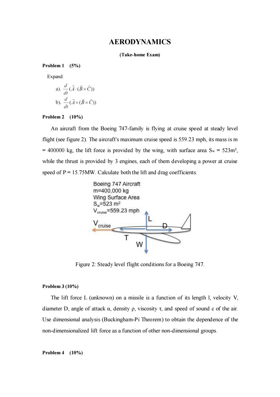
AERODYNAMICS (Take-home Exam) Problem 1 (5%) Expand: Problem 2 (10%) An aircraft from the Boeing 747-family is flying at cruise speed at steady level flight (see figure 2). The aircraft's maximum cruise speed is 559.23 mph, its mass is m = 400000 kg, the lift force is provided by the wing, with surface area Sw = 523m², while the thrust is provided by 3 engines, each of them developing a power at cruise speed of P = 15.75MW. Calculate both the lift and drag coefficients. Figure 2: Steady level flight conditions for a Boeing 747. Problem 3 (10%) The lift force L (unknown) on a missile is a function of its length l, velocity V, diameter D, angle of attack α, density ρ, viscosity τ, and speed of sound c of the air. Use dimensional analysis (Buckingham-Pi Theorem) to obtain the dependence of the non-dimensionalized lift force as a function of other non-dimensional groups. Problem 4 (10%)

It is known that for flow around blunt bodies at very high Reynolds numbers,the ribution at the win ward is very similar to the potential solution,while a the flow is detached.To evaluate the aerodynamic drag of a cable of circular section of radiusr=1cm(see figure 1)in a flow of uniform upstream velocity U=50m/s,densityp=1.2 kg/m3 and static pressure p=100kPa,it is assumed that the front side of the cable(windward<2)has a pressure coefficient Cp= 1-4sin0,while in the rear side (leeward)the flow is detached and the pressure coefficient is the value of the Cpat the detachment point(=2). U WINDWARD LEEWARD r P.P Figure 1:Flow around a circular cable a)Determine the aerodynamic drag coefficient by integrating Cp along the surface of the body b)Determine the drag force acting on the ylinder Problem5 (15%) High-lift devices are mechanisms intended to add lift during take-off and landing.The most common types ofhigh-lift devices are flaps and slats(see figure 1)
It is known that for flow around blunt bodies at very high Reynolds numbers, the pressure distribution at the windward is very similar to the potential solution, while at the leeward, the flow is detached. To evaluate the aerodynamic drag of a cable of circular section of radius r =1cm (see figure 1) in a flow of uniform upstream velocity U = 50m/s, density =1.2 kg/m3 and static pressure p =100kPa, it is assumed that the front side of the cable (windward 0< < /2) has a pressure coefficient Cp = 1- 4 2 sin , while in the rear side (leeward /2< < ) the flow is detached and the pressure coefficient is the value of the Cp at the detachment point ( = /2) . Figure 1: Flow around a circular cable a) Determine the aerodynamic drag coefficient by integrating Cp along the surface of the body. b) Determine the drag force acting on the cylinder. Problem 5 (15%) High-lift devices are mechanisms intended to add lift during take-off and landing. The most common types of high-lift devices are flaps and slats (see figure 1)

SLATS 9 Figure 1:Flaps and slats deployed in an Airbus A310 x=3c/4 -≥X I)Slat configuration ll)Flap configuration Figure2:Flap and Slat configurations Flaps increase the camber of the wing airfoil,thus increasing the if coefficient and allowing the aircraft to fly at lower speed by increasingAslat is equivalent to a flap but deployed at the leading edge. We will model both devices as seen in figure2.Slat deployment can be modeled as a flat plate with a deflection of angle B at x=c/4.Flap deployment can be modeled as a flat plate with a deflection of angle-Batx=3c/4
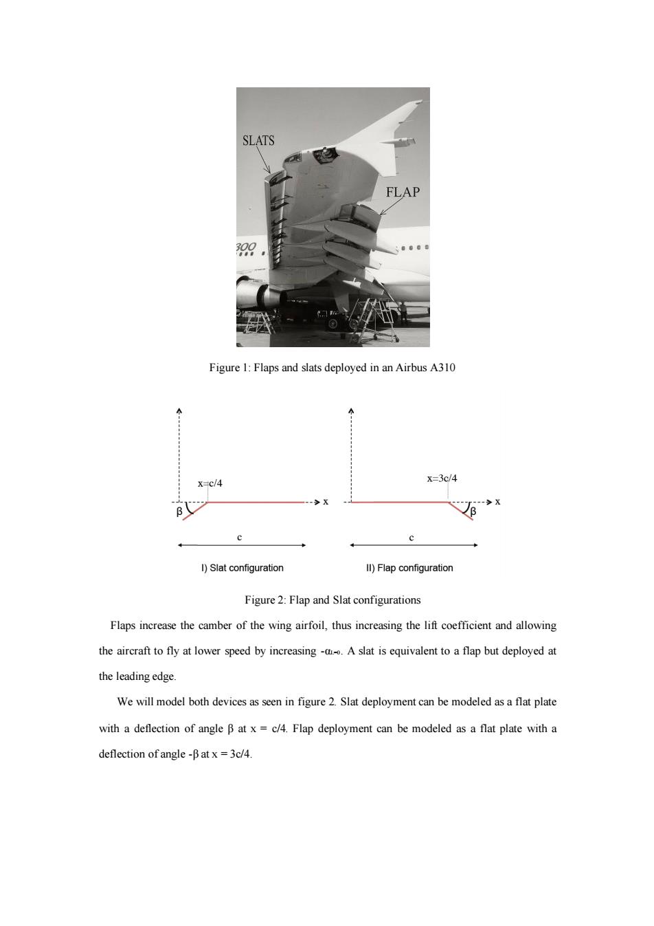
Figure 1: Flaps and slats deployed in an Airbus A310 Figure 2: Flap and Slat configurations Flaps increase the camber of the wing airfoil, thus increasing the lift coefficient and allowing the aircraft to fly at lower speed by increasing -αL=0. A slat is equivalent to a flap but deployed at the leading edge. We will model both devices as seen in figure 2. Slat deployment can be modeled as a flat plate with a deflection of angle β at x = c/4. Flap deployment can be modeled as a flat plate with a deflection of angle -β at x = 3c/4

Obthnand the moment coefcent about the aerodynamic cente Obtan the moment coelficient about the erodynamic cnter 3.How do the lift and moment coefficients compare in configuration I,configuration II and the no defection case (=0) After solving this problem,you should be able to see that a slat generates less extra lift than a flap.In fact,the function of the slat is a different one.A slat re-directs air from the lower part of the airfoil to the upper one at the leading edge,preventing boundary layer separation at a high angle of attack.This allows the wing to be operated effectively at higher angles attacka group o tarily at high Alula feathers Figure 3:Alula feathers in a landing male mallard. Problem 6(15%)
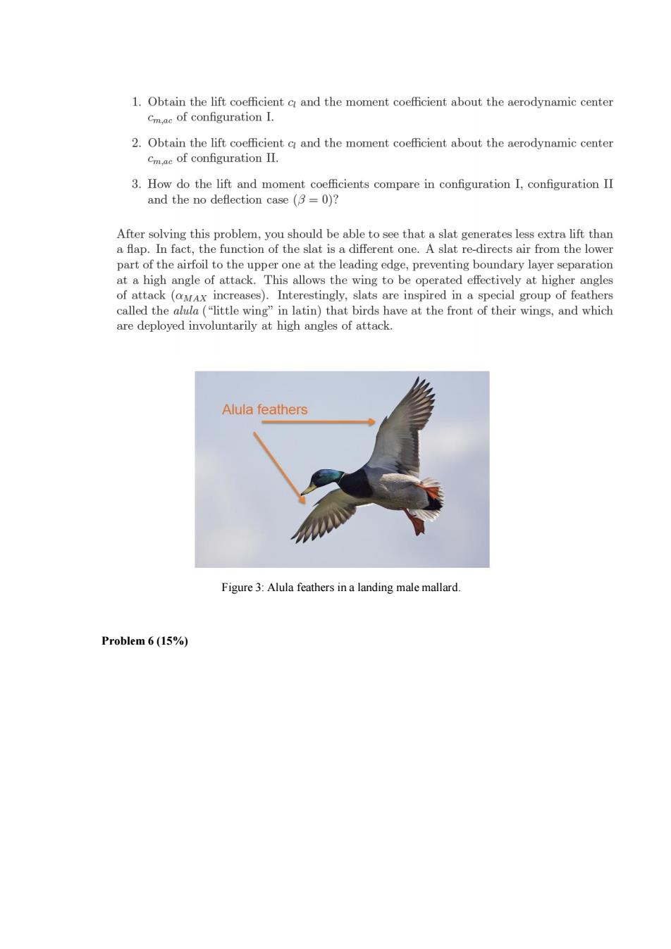
Figure 3: Alula feathers in a landing male mallard. Problem 6 (15%)

The camber line of an airfoil of chord c is defined as: z()=c(a-x)1-4r2) (2) where e<<1 and the airfoil located at sc/2.Obtain a in order to have the center of pressure at the same location than the aerodynamic center. = cos0 x= / x-ch2 Figure 4:Camber line centered at the origin Note that the camber line is centered at the origin(see figure)thus the transformation will be cos6 PROBLEM7(15%) velocity along the span direction is 0=-1++4g.=2c< 1.Obtain the value of the lift Lof the wing. 2.Determine the induced drag D in the wing 3.Calculate the roll moment about the axis M
PROBLEM 7 (15%)

PROBLEM 8 (20%) An aircraft is provided with a wing of elliptical planform shape,span band aspect ratio A>>1,is flying with velocity Uo in an ambient at rest.The wing sections are airfoils whose camber lines are shown in figure 1.The parameter 6(slope)varies along the spanwise direction as )=21-(gA,X 0 c/2 c Figure 1:Airfoil profile of an elliptical wing Provided that the chords of the different airfoil profiles are contained on a plane and that the orientation of that plane coincides with the direction of flight(a=0): 1.Using thin airfoil theory,obtain aL as a function of 6 2.Calculate the lift distribution L'(0). 3.Determine the zero lift angle of attack of the WHOLE wing. 4.Calculate the induced drag Di
PROBLEM 8 (20%)