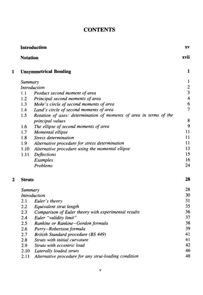
CONTENTS Introduction XV Notation Unsymmetrical Bending 1 Summary 1 Introduction 2 1.1 Product second moment of area 3 1.2 Principal second moments of area 1.3 Mohr's circle of second moments of area 6 1.4 Land's circle of second moments of area > 15 Rotation of axes:determination of moments of area in terms of the principal values 1.6 The ellipse of second moments of area 9 1.7 Momental ellipse 11 1.8 Stress determination 11 1.9 Alternative procedure for stress determination 11 1.10 Alternative procedure using the momental ellipse 13 1.11 Defections 15 Examples 16 Problems 24 Struts 28 Summary Introduction 2.1 Euler's theory 2301 2.2 Equivalent strut length 2.3 Comparison of Euler theory with experimental results 36 2.4 Euler "validity limit" 37 2.5 Rankine or Rankine-Gordon formula 2.6 Perry-Robertson formula 39 2.7 British Standard procedure (BS 449) 2.8 Struts with initial curvature 2.9 Struts with eccentric load 44126 2.10 Laterally loaded struts 2.11 Alternative procedure for any strut-loading condition 西
CONTENTS Introduction xv Notation xvii 1 Unsymmetrical Bending 1 Summary Introduction I .1 1.2 1.3 1.4 1.5 I .6 1.7 Momenta1 ellipse 1.8 Stress determination 1.9 Alternative procedure for stress determination 1.10 Alternative procedure using the momenta1 ellipse 1.1 1 Dejections Examples Problems Product second moment of area Principal second moments of area Mohr’s circle of second moments of area Land’s circle of second moments of area Rotation of axes: determination of moments of area in terms of the principal values The ellipse of second moments of area 2 Struts Summary Introduction 2.1 Euler’s theory 2.2 Equivalent strut length 2.3 2.4 Euler “validity limit” 2.5 Rankine or Rankine-Gordon formula 2.6 Perry- Robertson formula 2.7 2.8 Struts with initial curvature 2.9 Struts with eccentric load 2.10 Laterally loaded struts 2.1 1 Comparison of Euler theory with experimental results British Standard procedure (BS 449) Alternative procedure for any strut-loading condition 8 9 11 11 11 13 15 16 24 28 28 30 31 35 36 37 38 39 41 41 42 46 48 V
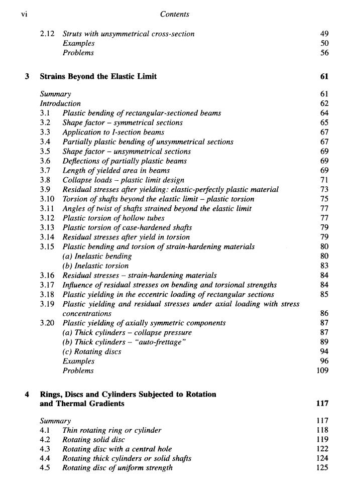
vi Contents 2.12 Struts with unsymmetrical cross-section 49 Examples 0 Problems 56 Strains Beyond the Elastic Limit 61 Summary 61 Introduction 62 3.1 Plastic bending of rectangular-sectioned beams 64 3.2 Shape factor-symmetrical sections 3.3 Application to I-section beams 61 3.4 Partially plastic bending of unsymmetrical sections 7 3.5 Shape factor-unsymmetrical sections 3.6 Deflections of partially plastic beams 69 3.7 Length of yielded area in beams 38 Collapse loads -plastic limit design 1 3.9 Residual stresses after yielding:elastic-perfectly plastic material 73 3.10 Torsion of shafts beyond the elastic limit-plastic torsion 3.11 Angles of twist of shafts strained beyond the elastic limit 3.12 Plastic torsion of hollow tubes 个 3.13 Plastic torsion of case-hardened shafts 3.14 Residual stresses after yield in torsion 7 3.15 Plastic bending and torsion of strain-hardening materials (a)Inelastic bending 6 (b)Inelastic torsion 83 3.16 Residual stresses-strain-hardening materials 84 3.17 Influence of residual stresses on bending and torsional strengths 84 3.18 Plastic yielding in the eccentric loading of rectangular sections 85 3.19 Plastic yielding and residual stresses under axial loading with stress concentrations 86 3.20 Plastic yielding of axially symmetric components 87 (a)Thick cylinders-collapse pressure 87 (b)Thick cylinders-"auto-frettage" 89 (c)Rotating discs 94 Examples 96 Problems 109 4 Rings,Discs and Cylinders Subjected to Rotation and Thermal Gradients 117 Summary 117 4.1 Thin rotating ring or cylinder 118 4.2 Rotating solid disc 119 4.3 Rotating disc with a central hole 122 4.4 Rotating thick cylinders or solid shafts 124 4.5 Rotating disc of uniform strength 125
vi Contents 2.1 2 Struts with unsymmetrical cross-section Examples Problems 3 Strains Beyond the Elastic Limit Summary Introduction 3.1 3.2 3.3 3.4 3.5 3.6 3.7 3.8 3.9 3.10 3.1 1 3.12 3.13 3.14 3.15 3.16 3.17 3.18 3.19 3.20 Plastic bending of rectangular-sectioned beams Shape factor - symmetrical sections Application to I-section beams Partially plastic bending of unsymmetrical sections Shape factor - unsymmetrical sections Dejections of partially plastic beams Length of yielded area in beams Collapse loads - plastic limit design Residual stresses after yielding: elastic-perfectly plastic material Torsion of shafts beyond the elastic limit - plastic torsion Angles of twist of shafts strained beyond the elastic limit Plastic torsion of hollow tubes Plastic torsion of case-hardened shafts Residual stresses after yield in torsion Plastic bending and torsion of strain-hardening materials (a) Inelastic bending (b) Inelastic torsion Residual stresses - strain-hardening materials Influence of residual stresses on bending and torsional strengths Plastic yielding in the eccentric loadirzg of rectangular sections Plastic yielding and residual stresses under axial loading with stress concentrations Plastic yielding of axially symmetric components (a) Thick cylinders - collapse pressure (b) Thick cylinders - “auto-frettage ’’ (c) Rotating discs Examples Problems 4 Rings, Discs and Cylinders Subjected to Rotation and Thermal Gradients Summary 4.1 4.2 Rotating solid disc 4.3 4.4 4.5 Thin rotating ring or cylinder Rotating disc with a central hole Rotating thick cylinders or solid shafs Rotating disc of uniform strength 49 50 56 61 61 62 64 65 67 67 69 69 69 71 73 75 77 77 79 79 80 80 83 84 84 85 86 87 87 89 94 96 109 117 117 118 119 122 124 125
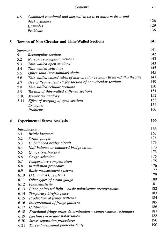
Contents vii 4.6 Combined rotational and thermal stresses in uniform discs and thick cylinders 126 Examples 129 Problems 136 5 Torsion of Non-Circular and Thin-Walled Sections 141 Summary 141 5.1 Rectangular sections 142 5.2 Narrow rectangular sections 143 5.3 Thin-walled open sections 143 5.4 Thin-walled split tube 145 5.5 Other solid(non-tubular)shafts 145 5.6 Thin-walled closed tubes of non-circular section (Bredt-Batho theory) 147 5.7 Use of "equivalent J"for torsion of non-circular sections 149 5.8 Thin-walled cellular sections 150 5.9 Torsion of thin-walled stiffened sections 151 5.10 Membrane analogy 152 5.11 Effect of warping of open sections 153 Examples 154 Problems 160 6 Experimental Stress Analysis 166 Introduction 166 6.1 Brittle lacquers 167 6.2 Strain gauges 171 6.3 Unbalanced bridge circuit 173 6.4 Null balance or balanced bridge circuit 173 6.5 Gauge construction 173 6.6 Gauge selection 175 6.7 Temperature compensation 175 6.8 Installation procedure 176 6.9 Basic measurement systems 177 6.10 D.C.and A.C.systems 179 6.11 Other types of strain gauge 180 6.12 Photoelasticity 181 6.13 Plane-polarised light-basic polariscope arrangements 182 6.14 Temporary birefringence 183 6.15 Production of fringe patterns 184 6.16 Interpretation of fringe patterns 185 6.17 Calibration 186 6.18 Fractional fringe order determination-compensation techniques 187 6.19 Isoclinics-circular polarisation 188 6.20 Stress separation procedures 190 6.21 Three-dimensional photoelasticity 190
Contents 4.6 Combined rotational and thermal stresses in uniform discs and thick cylinders Examples Problems 5 Torsion of Non-Circular and Thin- Walled Sections Summary 5.1 5.2 5.3 5.4 5.5 5.6 5.7 5.8 5.9 5.10 5.1 1 Rectangular sections Narrow rectangular sections Thin-walled open sections Thin-walled split tube Other solid (non-tubular) shafts Thin-walled closed tubes of non-circular section (Bredt-Batho theory) Use of “equivalent J” for torsion of non-circular sections Thin-walled cellular sections Torsion of thin-walled stifSened sections Membrane analogy EfSect of warping of open sections Examples Problems 6 Experimental Stress Analysis Introduction 6.1 6.2 6.3 6.4 6.5 6.6 6.7 6.8 6.9 6.10 6.1 1 6.12 6.13 6.14 6.15 6.16 6.17 6.18 6.19 6.20 6.21 Brittle lacquers Strain gauges Unbalanced bridge circuit Null balance or balanced bridge circuit Gauge construction Gauge selection Temperature compensation Installation procedure Basic measurement systems D.C. and A.C. systems Other types of strain gauge Photoelasticity Plane-polarised light - basic polariscope arrangements Temporary birefringence Production of fringe patterns Interpretation of fringe patterns Calibration Fractional fringe order determination - compensation techniques Isoclinics-circular polarisation Stress separation procedures Three-dimensional photoelasticity vii 126 129 136 141 141 142 143 143 145 145 147 149 150 151 152 153 154 160 166 166 167 171 173 173 173 175 175 176 177 179 180 181 182 183 184 185 186 187 188 190 1 90
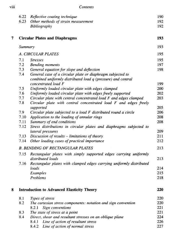
viii Contents 6.22 Reflective coating technique 190 6.23 Other methods of strain measurement 192 Bibliography 192 7 Circular Plates and Diaphragms 193 Summary 193 A.CIRCULAR PLATES 195 7.1 Stresses 195 7.2 Bending moments 197 7.3 General equation for slope and deflection 198 7.4 General case of a circular plate or diaphragm subjected to combined uniformly distributed load q(pressure)and central concentrated load F 199 7.5 Uniformly loaded circular plate with edges clamped 200 7.6 Uniformly loaded circular plate with edges freely supported 202 7.7 Circular plate with central concentrated load F and edges clamped 203 7.8 Circular plate with central concentrated load F and edges freely supported 205 7.9 Circular plate subjected to a load F distributed round a circle 206 7.10 Application to the loading of annular rings 208 7.11 Summary of end conditions 208 7.12 Stress distributions in circular plates and diaphragms subjected to lateral pressures 209 7.13 Discussion of results-limitations of theory 211 7.14 Other loading cases of practical importance 212 B.BENDING OF RECTANGULAR PLATES 213 7.15 Rectangular plates with simply supported edges carrying uniformly distributed loads 213 7.16 Rectangular plates with clamped edges carrying uniformly distributed loads 214 Examples 215 Problems 218 8 Introduction to Advanced Elasticity Theory 220 8.1 Types of stress 220 8.2 The cartesian stress components:notation and sign convention 220 8.2.1 Sign conventions 221 8.3 The state of stress at a point 221 8.4 Direct,shear and resultant stresses on an oblique plane 224 8.4.1 Line of action of resultant stress 226 8.4.2 Line of action of normal stress 227
... VI11 Contents 6.22 Rejective coating technique 6.23 Other methods of strain measurement Bibliography 7 Circular Plates and Diaphragms Summary A. CIRCULAR PLATES 7.1 7.2 7.3 7.4 7.5 7.6 7.7 7.8 7.9 7.10 7.1 1 7.12 7.13 7.14 Stresses Bending moments General equation for slope and dejection General case of a circular plate or diaphragm subjected to combined uniformly distributed load q (pressure) and central concentrated load F Uniformly loaded circular plate with edges clamped Uniformly loaded circular plate with edges freely supported Circular plate with central concentrated load F and edges clamped Circular plate with central concentrated load F and edges freely supported Circular plate subjected to a load F distributed round a circle Application to the loading of annular rings Summary of end conditions Stress distributions in circular plates and diaphragms subjected to lateral pressures Discussion of results - limitations of theory Other loading cases of practical importance B. BENDING OF RECTANGULAR PLATES 7.15 7.16 Rectangular plates with simply supported edges carrying uniformly distributed loads Rectangular plates with clamped edges carrying uniformly distributed loads Examples Problems 8 Introduction to Advanced Elasticity Theory 8.1 Types of stress 8.2 8.3 8.4 The Cartesian stress components: notation and sign convention 8.2.1 Sign conventions The state of stress at a point Direct, shear and resultant stresses on an oblique plane 8.4.1 8.4.2 Line of action of resultant stress Line of action of normal stress 190 192 192 193 193 195 195 197 198 199 200 202 203 205 206 208 208 209 21 1 212 213 213 214 215 218 220 220 220 22 1 22 1 224 226 227
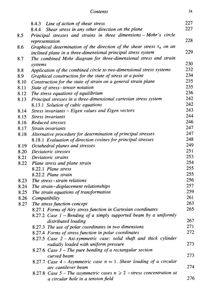
Contents ix 8.4.3 Line of action of shear stress 227 8.4.4 Shear stress in any other direction on the plane 227 8.5 Principal stresses and strains in three dimensions-Mohr's circle representation 228 8.6 Graphical determination of the direction of the shear stress tn on an inclined plane in a three-dimensional principal stress system 229 8.7 The combined Mohr diagram for three-dimensional stress and strain systems 230 8.8 Application of the combined circle to two-dimensional stress systems 232 8.9 Graphical construction for the state of stress at a point 234 8.10 Construction for the state of strain on a general strain plane 235 8.11 State of stress-tensor notation 235 8.12 The stress equations of equilibrium 236 8.13 Principal stresses in a three-dimensional cartesian stress system 242 8.13.1 Solution of cubic equations 242 8.14 Stress invariants-Eigen values and Eigen vectors 243 8.15 Stress invariants 244 8.16 Reduced stresses 246 8.17 Strain invariants 247 8.18 Alternative procedure for determination of principal stresses 247 8.18.1 Evaluation of direction cosines for principal stresses 248 8.19 Octahedral planes and stresses 249 8.20 Deviatoric stresses 251 8.21 Deviatoric strains 253 8.22 Plane stress and plane strain 254 8.22.1 Plane stress 255 8.22.2 Plane strain 255 8.23 The stress-strain relations 256 8.24 The strain-displacement relationships 257 8.25 The strain equations of transformation 259 8.26 Compatibility 261 8.27 The stress function concept 263 8.27.1 Forms of Airy stress function in Cartesian coordinates 265 8.27.2 Case I-Bending of a simply supported beam by a uniformly distributed loading 267 8.27.3 The use of polar coordinates in two dimensions 271 8.27.4 Forms of stress function in polar coordinates 272 8.27.5 Case 2-Axi-symmetric case:solid shaft and thick cylinder radially loaded with uniform pressure 273 8.27.6 Case 3-The pure bending of a rectangular section curved beam 273 8.27.7 Case 4-Asymmetric case n =1.Shear loading of a circular arc cantilever beam 274 8.27.8 Case 5-The asymmetric cases n >2 -stress concentration at a circular hole in a tension field 276
Contents ix 8.5 8.6 8.7 8.8 8.9 8.10 8.1 1 8.12 8.13 8.14 8.15 8.16 8.17 8.18 8.19 8.20 8.21 8.22 8.23 8.24 8.25 8.26 8.27 8.4.3 8.4.4 Principal stresses and strains in three dimensions - Mohr 's circle representation Graphical determination of the direction of the shear stress r,, on an inclined plane in a three-dimensional principal stress system The combined Mohr diagram for three-dimensional stress and strain systems Application of the combined circle to two-dimensional stress systems Graphical construction for the state of stress at a point Construction for the state of strain on a general strain plane State of stress-tensor notation The stress equations of equilibrium Principal stresses in a three-dimensional Cartesian stress system 8.13.1 Solution of cubic equations Stress invariants - Eigen values and Eigen vectors Stress invariants Reduced stresses Strain invariants Alternative procedure for determination of principal stresses 8.1 8.1 Evaluation of direction cosines for principal stresses Octahedral planes and stresses Deviatoric stresses Deviatoric strains Plane stress and plane strain 8.22.1 Plane stress 8.22.2 Plane strain The stress-strain relations The strain-displacement relationships The strain equations of transformation Compatibility The stress function concept 8.27.1 Forms of Airy stress function in Cartesian coordinates 8.27.2 Case 1 - Bending of a simply supported beam by a uniformly 8.27.3 The use of polar coordinates in two dimensions 8.27.4 Forms of stress function in polar coordinates 8.27.5 Case 2 - hi-symmetric case: solid shaft and thick cylinder radially loaded with uniform pressure 8.27.6 Case 3 - The pure bending of a rectangular section curved beam 8.27.7 Case 4 - Asymmetric case n = 1. Shear loading of a circular arc cantilever beam 8.27.8 Case 5 - The asymmetric cases n >, 2 -stress concentration at a circular hole in a tension$eld Line of action of shear stress Shear stress in any other direction on the plane distributed loading 227 227 228 229 230 232 234 235 235 236 242 242 243 244 246 247 247 248 249 25 1 25 3 254 255 255 256 257 259 26 1 263 265 267 27 1 272 273 273 274 276
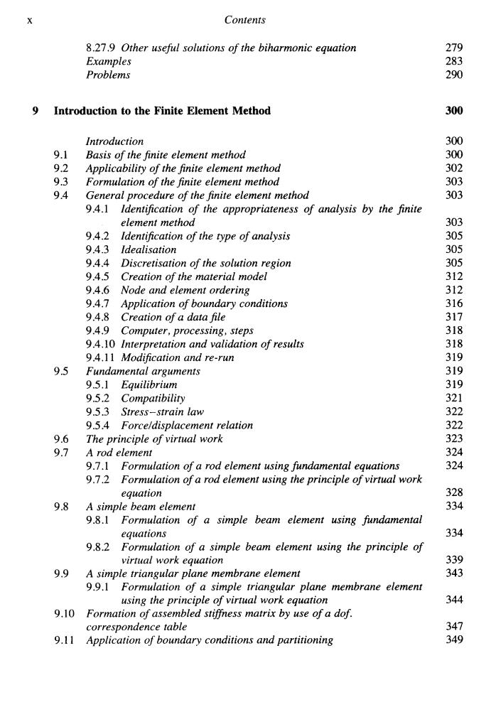
Contents 8.27.9 Other useful solutions of the biharmonic equation 279 Examples 283 Problems 290 Introduction to the Finite Element Method 300 Introduction 300 9.1 Basis of the finite element method 300 9.2 Applicability of the finite element method 302 9.3 Formulation of the finite element method 303 9.4 General procedure of the finite element method 303 9.4.1 Identification of the appropriateness of analysis by the finite element method 303 9.4.2 Identification of the type of analysis 305 94.3 Idealisation 305 9.4.4 Discretisation of the solution region 305 9.4.5 Creation of the material model 312 9.4.6 Node and element ordering 312 9.4.7 Application of boundary conditions 316 9.4.8 Creation of a data file 317 9.4.9 Computer,processing,steps 318 9.4.10 Interpretation and validation of results 318 94.11 Modification and re-run 319 9.5 Fundamental arguments 319 9.5.】Equilibrium 319 9.5.2 Compatibility 321 9.5.3 Stress-strain law 322 9.5.4 Forceldisplacement relation 322 9.6 The principle of virtual work 323 9.7 A rod element 324 9.7.1 Formulation of a rod element using fundamental equations 324 9.7.2 Formulation of a rod element using the principle of virtual work equation 328 9.8 A simple beam element 334 9.8.1 Formulation of a simple beam element using fundamental equations 334 9.8.2 Formulation of a simple beam element using the principle of virtual work equation 339 9.9 A simple triangular plane membrane element 343 9.9.1 Formulation of a simple triangular plane membrane element using the principle of virtual work equation 344 9.10 Formation of assembled stiffness matrix by use of a dof. correspondence table 347 9.11 Application of boundary conditions and partitioning 349
X Contents 8.27.9 Other useful solutions of the biharmonic equation Examples Problems 9 Introduction to the Finite Element Method 9.1 9.2 9.3 9.4 9.5 9.6 9.7 9.8 9.9 9.10 9.1 1 Introduction Basis of the finite element method Applicability of the finite element method Formulation of the Jinite element method General procedure of the Jinite element method 9.4.1 Identification of the appropriateness of analysis by the jinite element method 9.4.2 Identification of the type of analysis 9.4.3 Idealisation 9.4.4 Discretisation of the solution region 9.4.5 Creation of the material model 9.4.6 Node and element ordering 9.4.7 Application of boundary conditions 9.4.8 Creation of a data file 9.4.9 Computer, processing, steps 9.4.10 Interpretation and validation of results 9.4.1 1 Modification and re-run Fundamental arguments 9.5.1 Equilibrium 9.5.2 Compatibility 9.5.3 Stress-strain law 9.5.4 Forceldisplacement relation The principle of virtual work A rod element 9.7.1 Formulation of a rod element using fundamental equations 9.7.2 Formulation of a rod element using the principle of virtual work equation A simple beam element 9.8.1 Formulation of a simple beam element using fundamental equations 93.2 Formulation of a simple beam element using the principle of virtual work equation A simple triangular plane membrane element 9.9.1 Formulation of a simple triangular plane membrane element using the principle of virtual work equation Formation of assembled stcfiess matrix by use of a dof. correspondence table Amlieation of boundarv conditions and uartitioninn r, " 279 283 290 300 300 300 302 303 303 303 305 305 305 312 312 316 317 318 318 319 319 319 321 322 322 323 324 324 32% 334 3 34 339 343 344 347 349
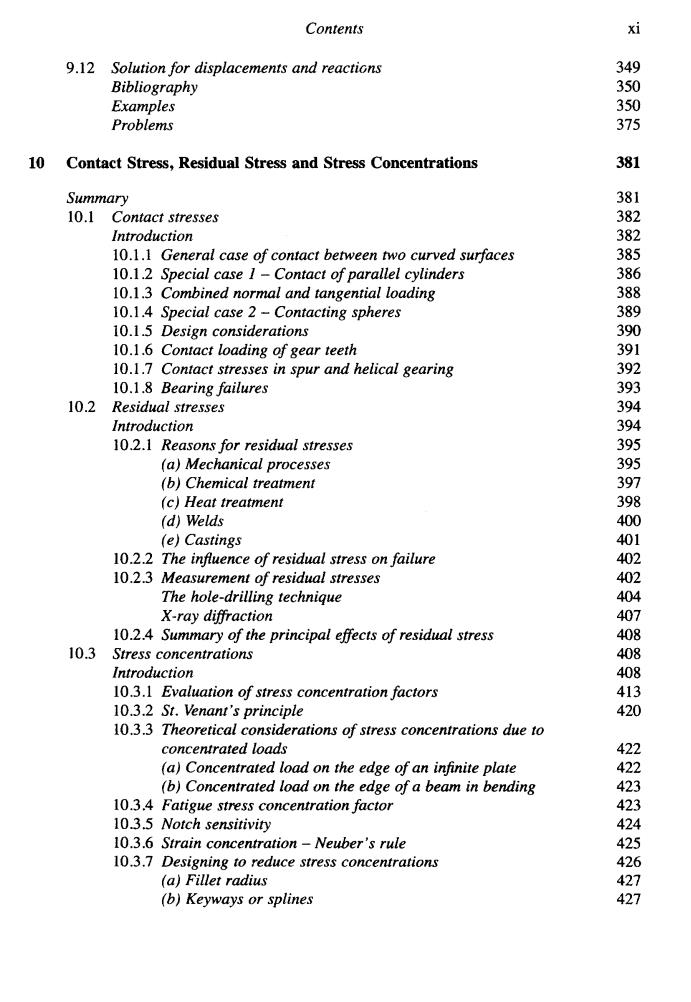
Contents xi 9.12 Solution for displacements and reactions 349 Bibliography 350 Examples 350 Problems 375 10 Contact Stress,Residual Stress and Stress Concentrations 381 Summary 381 10.1 Contact stresses 382 Introduction 382 10.1.1 General case of contact between two curved surfaces 385 10.1.2 Special case 1-Contact of parallel cylinders 386 10.1.3 Combined normal and tangential loading 388 10.1.4 Special case 2-Contacting spheres 389 10.1.5 Design considerations 10.1.6 Contact loading of gear teeth 10.1.7 Contact stresses in spur and helical gearing 10.1.8 Bearing failures 10.2 Residual stresses 394 Introduction 10.2.1 Reasons for residual stresses (a)Mechanical processes (b)Chemical treatment (c)Heat treatment 40909090800 (d)Welds (e)Castings 10.2.2 The influence of residual stress on failure 10.2.3 Measurement of residual stresses 咖 The hole-drilling technique X-ray diffraction 81 10.2.4 Summary of the principal effects of residual stress 408 10.3 Stress concentrations 408 Introduction 408 10.3.1 Evaluation of stress concentration factors 413 10.3.2 St.Venant's principle 420 10.3.3 Theoretical considerations of stress concentrations due to concentrated loads 422 (a)Concentrated load on the edge of an infinite plate 422 (b)Concentrated load on the edge of a beam in bending 423 10.3.4 Fatigue stress concentration factor 423 10.3.5 Notch sensitivity 424 10.3.6 Strain concentration-Neuber's rule 425 10.3.7 Designing to reduce stress concentrations 426 (a)Fillet radius 427 (b)Keyways or splines 427
Contents xi 9.12 Solution for displacements and reactims Bibliography Examples Problems 10 Contact Stress, Residual Stress and Stress Concentrations Summary 10.1 Contact stresses Introduction 10.1.1 General case of contact between two curved surfaces 10.1.2 Special case I - Contact of parallel cylinders 10.1.3 Combined normal and tangential loading 10.1.4 Special case 2 - Contacting spheres 10.1.5 Design considerations 10.1.6 Contact loading of gear teeth 10.1.7 Contact stresses in spur and helical gearing 10.1.8 Bearing failures Introduction 10.2.1 Reasom for residual stresses (a) Mechanical processes (b) Chemical treatment (c) Heat treatment (d) Welds (e) Castings 10.2 Residual stresses 10.2.2 The injuence of residual stress on failure 10.2.3 Measurement of residual stresses The hole-drilling technique X-ray difiaction 10.2.4 Summary of the principal effects of residual stress Introduction 10.3.1 Evaluation of stress concentration factors 10.3.2 St. Venant 's principle 10.3.3 Theoretical considerations of stress concentrations due to 10.3 Stress concentrations concentrated loads (a) Concentrated load on the edge of an infinite plate (b) Concentrated load on the edge of a beam in bending 10.3.4 Fatigue stress concentration factor 10.3.5 Notch sensitivity 10.3.6 Strain concentration - Neuber 's rule 10.3.7 Designing to reduce stress concentrations (a) Fillet radius (b) Keyways or splines 349 350 350 375 381 38 1 382 382 385 386 388 389 390 39 1 392 393 394 394 395 395 397 398 400 401 402 402 404 407 408 408 408 413 420 422 422 423 423 424 425 426 427 427

xii Contents (c)Grooves and notches 429 (d)Gear teeth 430 (e)Holes 431 (f)Oil holes 431 (g)Screw threads 431 (h)Press or shrink fit members 433 10.3.8 Use of stress concentration factors with yield criteria 434 10.3.9 Design procedure 434 References 435 Examples 437 Problems 442 11 Fatigue,Creep and Fracture 443 Summary 443 11.1 Fatigue 446 Introduction 446 11.1.1 The S/N curve 446 11.1.2 P/S/N curves 449 11.1.3 Effect of mean stress 451 11.1.4 Effect of stress concentration 453 11.1.5 Cumulative damage 454 11.1.6 Cyclic stress-strain 455 11.1.7 Combating fatigue 458 11.1.8 Slip bands and fatigue 460 11.2 Creep 462 Introduction 462 11.2.1 The creep test 462 11.2.2 Presentation of creep data 465 11.2.3 The stress-rupture test 466 11.2.4 Parameter methods 467 11.2.5 Stress relaxation 470 11.2.6 Creep-resistant alloys 471 11.3 Fracture mechanics 472 Introduction 472 11.3.1 Energy variation in cracked bodies 473 (a)Constant displacement 474 (b)Constant loading 474 11.3.2 Linear elastic fracture mechanics (L.E.F.M.) 475 (a)Griffith's criterion for fracture 475 (b)Stress intensity factor 477 11.3.3 Elastic-plastic fracture mechanics (E.P.F.M.) 481 11.3.4 Fracture toughness 483 11.3.5 Plane strain and plane stress fracture modes 484 11.3.6 General yielding fracture mechanics 484 11.3.7 Fatigue crack growth 486 11.3.8 Crack tip plasticity under fatigue loading 488
xii Contents (e) Grooves and notches (d) Gear teeth (e) Holes cf) Oil holes (g) Screw threads (h) Press or shrink Jit members 10.3.8 Use of stress concentration factors with yield criteria 10.3.9 Design procedure References Examples Problems 11 Fatigue, Creep and Fracture Summary 11.1 Fatigue Introduction 11.1.1 The SIN curve 1 1.1.2 PISIN curves 1 1.1.3 Effect of mean stress 1 1.1.4 Effect of stress concentration 11.1.5 Cumulative damage 1 1.1.6 Cyclic stress-strain 1 1.1.7 Combating fatigue 1 1.1.8 Slip bands and fatigue Introduction 1 1.2.1 The creep test 1 1.2.2 Presentation of creep data 11.2.3 The stress-rupture test 11.2.4 Parameter methods 1 1.2.5 Stress relaxation 1 1.2.6 Creep-resistant alloys 1 1.3 Fracture mechanics Introduction 1 1.3.1 Energy variation in cracked bodies (a) Constant displacement (b) Constant loading (a) Grifith 's criterion for fiacture (b) Stress intensity factor 11.2 Creep 1 1.3.2 Linear elastic fracture mechanics (L.E.F.M.) 1 1.3.3 Elastic-plastic fracture mechanics (E.P.F.M.) 1 1.3.4 Fracture toughness 1 1.3.5 Plane strain and plane stress fracture modes 1 1.3.6 General yielding fracture mechanics 1 1.3.7 Fatigue crack growth 1 1.3.8 Crack tip plasticity under fatigue loading 429 430 43 1 43 1 43 1 433 434 434 435 437 442 443 443 446 446 446 449 45 1 453 454 455 458 460 462 462 462 465 466 467 470 47 1 472 472 473 474 474 475 475 477 48 1 483 484 484 486 488

Contents xiii 11.3.9 Measurement of fatigue crack growth 489 References 490 Examples 491 Problems 503 12 Miscellaneous topics 509 12.1 Bending of beams with initial curvature 509 12.2 Bending of wide beams 515 12.3 General expression for stresses in thin-walled shells subjected to pressure or self-weight 517 12.4 Bending stresses at discontinuities in thin shells 518 12.5 Viscoelasticity 521 References 527 Examples 527 Problems 527 Appendix 1.Typical mechanical and physical properties for engineering metals 534 Appendix 2. Typical mechanical properties of non-metals 535 Appendix 3.Other properties of non-metals 536 Index 537
... Contents Xlll 11.3.9 Measurement of fatigue crack growth References Examples Problems 489 490 49 1 503 12 Miscellaneous topics 509 12.1 Bending of beams with initial curvature 12.2 Bending of wide beams 12.3 General expression for stresses in thin-walled pressure or selj-weight 12.4 Bending stresses at discontinuities in thin shells 1 2.5 Viscoelasticity References Examples Problems 509 515 517 518 521 527 527 527 shells subjected to Appendix 1. npical mechanical and physical properties for engineering metals Appendix 2. Typical mechanical properties of non-metals Appendix 3. Other properties of non-metals 534 535 536 Index 537