
CHAPTER 2 STRUTS Summary The allowable stresses and end loads given by Euler's theory for struts with varying end conditions are given in Table 2.1. Table 2.1. End condition Fixed-free Pinned-pinned Fixed-pinned Fixed-fixed (or rounded) π2E1 T2El 2π2E1 4π2E1 4L2 L2 L2 L2 Euler load Pe or,writing /=Ak2,wherek=radius of gyration π2EA R2EA 2π2EA 4n2EA 4(L/k)2 (L/k2 (L/k) (L/k)2 Euler stress n2E nπ2E 2π2E 4n2E 4(L/k)2 (L/k2 (L/k)2 (L/k)2 Here L is the length of the strut and the term L/k is known as the slenderness ratio. Validity limit for Euler formulae where C is a constant depending on the end condition of the strut. Rankine-Gordon Formula Oy O= 1+a(L/k)2 where a=(o/2E)theoretically but is usually found by experiment.Typical values are given in Table 2.2. Table 2.2. Material Compressive yield stress (MN/m2) Pinned ends Fixed ends Mild steel 315 1/7500 1/30000 Cast iron 540 1/1600 1/64000 Timber 35 1/3000 1/12000 N.B.The value of for pinned ends is always four times that for fixed ends 28
CHAPTER 2 STRUTS End condition Summary Fixed-free Pinned-pinned Fixed-pinned Fixed-fixed T~EI X~EI 2n2EI 4n2EI 4L2 L2 L2 L2 (or rounded) ~ ~ ~ ~ The allowable stresses and end loads given by Euler’s theory for struts with varying end conditions are given in Table 2.1. Table 2.1. Euler load P, I or, writing I = Ak2, where k = radius of gyration Here L is the length of the strut and the term L/k is known as the slenderness ratio. Validity limit for Euler formulae where C is a constant depending on the end condition of the strut. Rankine -Gordon Formula *?, o= 1 + U(L/k)* where a = (o,./n2E) theoretically but is usually found by experiment. Typical values are given in Table 2.2. Table 2.2 Material Cast iron Timber Compressive yield stress Pinned ends Fixed ends 1/7500 1 /30 000 1 /64 000 1/12000 N.B. The value of II for pinned ends is always four times that for tixed ends 28
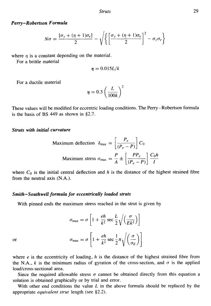
Struts 29 Perry-Robertson Formula Na=loy+(n+1)0.] 2 V+g+- where n is a constant depending on the material. For a brittle material n=0.015L/k For a ductile material n=0.3 100k These values will be modified for eccentric loading conditions.The Perry-Robertson formula is the basis of BS 449 as shown in 82.7. Struts with initial curvature Maximum deflection max= Pe Co L(Pe-P) P Maximum stress omax PPe Coh (P。-P)I where Co is the initial central deflection and h is the distance of the highest strained fibre from the neutral axis (N.A.). Smith-Southwell formula for eccentrically loaded struts With pinned ends the maximum stress reached in the strut is given by a=l+尝c5/(品) 0 m=l+装√( where e is the eccentricity of loading,h is the distance of the highest strained fibre from the N.A.,k is the minimum radius of gyration of the cross-section,and o is the applied load/cross-sectional area. Since the required allowable stress o cannot be obtained directly from this equation a solution is obtained graphically or by trial and error. With other end conditions the value L in the above formula should be replaced by the appropriate equivalent strut length (see $2.2)
Struts Perry-Robertson Formula 29 where q is a constant depending on the material. For a brittle material q = 0.015L/k For a ductile material 2 t) = 0.3 (&) These values will be modified for eccentric loading conditions. The Perry-Robertson formula is the basis of BS 449 as shown in $2.7. Struts with initial curvature Maximum deflection 6,, = Maximum stress amax = - f where CO is the initial central deflection and h is the distance of the highest strained fibre from the neutral axis (N.A.). Smith-Southwell formula for eccentrically loaded struts With pinned ends the maximum stress reached in the strut is given by a,,, = 0 [ 1 + - : sec - :/(&I] or where e is the eccentricity of loading, h is the distance of the highest strained fibre from the N.A., k is the minimum radius of gyration of the cross-section, and o is the applied loadkross-sectional area. Since the required allowable stress a cannot be obtained directly from this equation a solution is obtained graphically or by trial and error. With other end conditions the value L in the above formula should be replaced by the appropriate equivalent strut length (see 52.2)
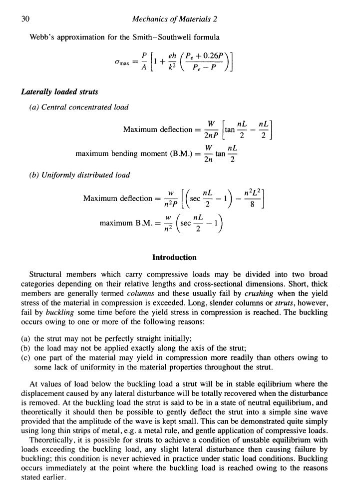
30 Mechanics of Materials 2 Webb's approximation for the Smith-Southwell formula -+(引 Laterally loaded struts (a)Central concentrated load W nL n Maximum deflection tan 2nP 2 2 maximum bending moment (B.M.)= 2n tan 2 (b)Uniformly distributed load Maximum deflection nL maximum B.M. n2 Introduction Structural members which carry compressive loads may be divided into two broad categories depending on their relative lengths and cross-sectional dimensions.Short,thick members are generally termed columns and these usually fail by crushing when the yield stress of the material in compression is exceeded.Long,slender columns or struts,however, fail by buckling some time before the yield stress in compression is reached.The buckling occurs owing to one or more of the following reasons: (a)the strut may not be perfectly straight initially; (b)the load may not be applied exactly along the axis of the strut; (c)one part of the material may yield in compression more readily than others owing to some lack of uniformity in the material properties throughout the strut. At values of load below the buckling load a strut will be in stable eqilibrium where the displacement caused by any lateral disturbance will be totally recovered when the disturbance is removed.At the buckling load the strut is said to be in a state of neutral equilibrium,and theoretically it should then be possible to gently deflect the strut into a simple sine wave provided that the amplitude of the wave is kept small.This can be demonstrated quite simply using long thin strips of metal,e.g.a metal rule,and gentle application of compressive loads. Theoretically,it is possible for struts to achieve a condition of unstable equilibrium with loads exceeding the buckling load,any slight lateral disturbance then causing failure by buckling;this condition is never achieved in practice under static load conditions.Buckling occurs immediately at the point where the buckling load is reached owing to the reasons stated earlier
30 Mechanics of Materials 2 Webb's approximation for the Smith-Southwell formula P, + 0.26P omax=! [I+$( p,-p )] A Laterally loaded struts (a) Central concentrated load Maximum deflection = 2n P W nL maximum bending moment (B.M.) = - tan - 2n 2 (6) Uniformly distributed load Maximum deflection = maximum B.M. = sec - - 1 n "( ) Introduction Structural members which carry compressive loads may be divided into two broad categories depending on their relative lengths and cross-sectional dimensions. Short, thick members are generally termed columns and these usually fail by crushing when the yield stress of the material in compression is exceeded. Long, slender columns or struts, however, fail by buckling some time before the yield stress in compression is reached. The buckling occurs owing to one or more of the following reasons: (a) the strut may not be perfectly straight initially; (b) the load may not be applied exactly along the axis of the strut; (c) one part of the material may yield in compression more readily than others owing to some lack of uniformity in the material properties throughout the strut. At values of load below the buckling load a strut will be in stable eqilibrium where the displacement caused by any lateral disturbance will be totally recovered when the disturbance is removed. At the buckling load the strut is said to be in a state of neutral equilibrium, and theoretically it should then be possible to gently deflect the strut into a simple sine wave provided that the amplitude of the wave is kept small. This can be demonstrated quite simply using long thin strips of metal, e.g. a metal rule, and gentle application of compressive loads. Theoretically, it is possible for struts to achieve a condition of unstable equilibrium with loads exceeding the buckling load, any slight lateral disturbance then causing failure by buckling; this condition is never achieved in practice under static load conditions. Buckling occurs immediately at the point where the buckling load is reached owing to the reasons stated earlier

$2.1 Struts 31 The above comments and the contents of this chapter refer to the elastic stability of struts only.It must also be remembered that struts can also fail plastically,and in this case the failure is irreversible. 2.1.Euler's theory (a)Strut with pinned ends Consider the axially loaded strut shown in Fig.2.1 subjected to the crippling load Pe producing a deflection y at a distance x from one end.Assume that the ends are either pin-jointed or rounded so that there is no moment at either end. y Fig.2.1.Strut with axial load and pinned ends. B.M.at C=E/ d2y dx2 =-Pey d2y xz+Pey=0 EI d2y Pe Eiy÷0 i.e.in operator form,with D=d/dx, (D2 +n2)y=0.where n2=Pe/EI This is a second-order differential equation which has a solution of the form y A cos nx +B sinnx i.e. Now atx=0,y=0 .A=0 and atx=L,y=0 .B sin L√/(Pe/E)=0 either B=0 or sin =0 If B=0 then y =0 and the strut has not yet buckled.Thus the solution required is ny()-0/()= π2E1 P= (2.1)
52.1 Struts 31 The above comments and the contents of this chapter refer to the elastic stability of struts only. It must also be remembered that struts can also fail plastically, and in this case the failure is irreversible. 2.1. Euler’s theory (a) Strut with pinned ends Consider the axially loaded strut shown in Fig. 2.1 subjected to the crippling load P, producing a deflection y at a distance x from one end. Assume that the ends are either pin-jointed or rounded so that there is no moment at either end. Fig. 2.1. Strut with axial load and pinned ends. .. d2 Y B.M. at C = EI- = -Pey dx2 EI-+Pey=O d2 Y dx2 .. Le. in operator form, with D d/dx, (D2 + n2)y = 0, where n2 = PJEI This is a second-order differential equation which has a solution of the form y = A cosnx + B sin nx i.e. Now at x = 0, y = 0 and at x = L, y = 0 Y = A cos ,/( $)x + B sin ,/( $)x :. A = 0 :. B sin L,/(Pe/EZ) = 0 .. either B = 0 or sinL If B = 0 then y = 0 and the strut has not yet buckled. Thus the solution required is 2EZ P, = - L2
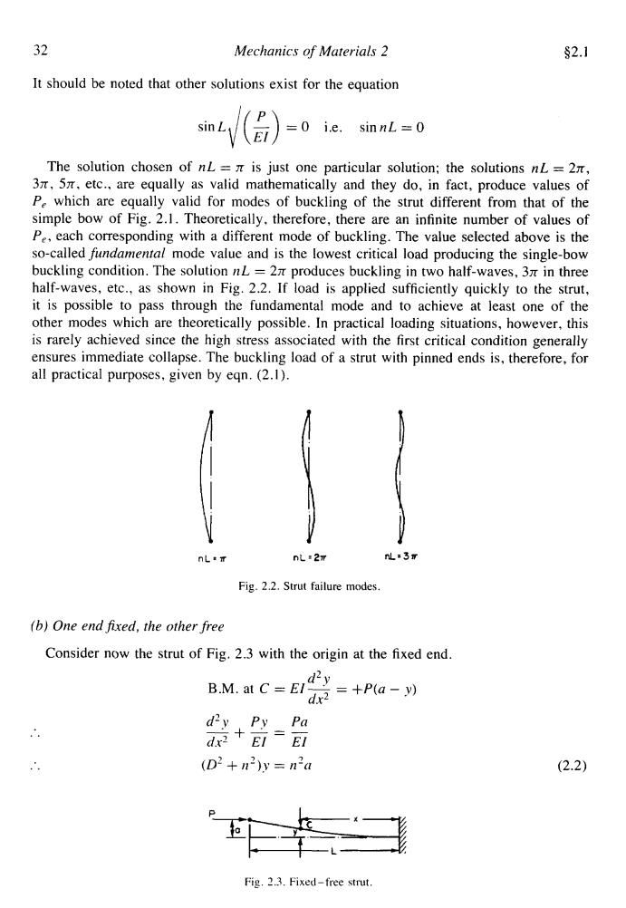
32 Mechanics of Materials 2 $2.1 It should be noted that other solutions exist for the equation =0 i.e. sin nL=0 The solution chosen of nL=x is just one particular solution;the solutions nL=2n, 3,5x.etc.,are equally as valid mathematically and they do,in fact,produce values of Pe which are equally valid for modes of buckling of the strut different from that of the simple bow of Fig.2.1.Theoretically.therefore,there are an infinite number of values of Pe,each corresponding with a different mode of buckling.The value selected above is the so-called fundamental mode value and is the lowest critical load producing the single-bow buckling condition.The solution nL =2 produces buckling in two half-waves,3x in three half-waves,etc.,as shown in Fig.2.2.If load is applied sufficiently quickly to the strut, it is possible to pass through the fundamental mode and to achieve at least one of the other modes which are theoretically possible.In practical loading situations,however,this is rarely achieved since the high stress associated with the first critical condition generally ensures immediate collapse.The buckling load of a strut with pinned ends is,therefore,for all practical purposes,given by eqn.(2.1). nL:T nL:2T nL:3m Fig.2.2.Strut failure modes. (b)One end fixed,the other free Consider now the strut of Fig.2.3 with the origin at the fixed end. B.M.at C=EI d-y dx2 =+P(a-y) d2y Py Pa dx+El=El (D2+n2)y n2a (2.2) Fig.2.3.Fixed-free strut
32 Mechanics of Materials 2 92.1 It should be noted that other solutions exist for the equation The solution chosen of nL = T is just one particular solution; the solutions nL = 2~, 317, 517, etc., are equally as valid mathematically and they do, in fact, produce values of P, which are equally valid for modes of buckling of the strut different from that of the simple bow of Fig. 2.1. Theoretically, therefore, there are an infinite number of values of P,, each corresponding with a different mode of buckling. The value selected above is the so-called fundamental mode value and is the lowest critical load producing the single-bow buckling condition. The solution rzL = 237 produces buckling in two half-waves, IT in three half-waves, etc., as shown in Fig. 2.2. If load is applied sufficiently quickly to the strut, it is possible to pass through the fundamental mode and to achieve at least one of the other modes which are theoretically possible. In practical loading situations, however, this is rarely achieved since the high stress associated with the first critical condition generally ensures immediate collapse. The buckling load of a strut with pinned ends is, therefore, for all practical purposes, given by eqn. (2.1). nL=27r Fig. 2.2. Strut failure modes. (6) One endJiued, the other free Consider now the strut of Fig. 2.3 with the origin at the fixed end. .. .. Fig. 7.3. Fixed-free strut

§21 Struts 33 N.B.-It is always convenient to arrange the diagram and origin such that the differential equation is achieved in the above form since the solution will then always be of the form y A cos nx+B sin nx +(particular solution) The particular solution is a particular value of y which satisfies eqn.(2.2),and in this case can be shown to be y =a. y A cos nx B sin nx+a Now whenx=0,y=0 A=-a when x =0,dy/dx =0 B=0 y =-acosnx +a But whenx=L,y=a a=-acosnL+a 0=cosnL The fundamental mode of buckling in this case therefore is given when nL = xEI or Pe= 4L2 (2.3) (c)Fixed ends Consider the strut of Fig.2.4 with the origin at the centre. Fig.2.4.Strut with fixed ends. In this case the B.M.at C is given by dx2=M-Py d2y P M dx2+Ely=Ei (D2+n2)y=M/EI
$2.1 Struts 33 N.B.-It is always convenient to arrange the diagram and origin such that the differential equation is achieved in the above form since the solution will then always be of the form y = A cos nx + B sin nx + (particular solution) The particular solution is a particular value of y which satisfies eqn. (2.2), and in this case can be shown to be y = a. .. Now when x = 0, y = 0 .. A = -a when x = 0, dyldx = 0 .. B=O .. y=-acosnx+a But when x = L, y = a .. a = -acosnL +a y = A cosnx + B sinrzx + a 0 = cosnL The fundamental mode of buckling in this case therefore is given when nL = in. or ~EI P, = - 4LZ (c) Fixed ends Consider the strut of Fig. 2.4 with the origin at the centre. Fig. 2.4. Strut with fixed ends. In this case the B.M. at C is given by (2.3) d2y P A4 dx2 El (D2 + n2)y = M/EI

34 Mechanics of Materials 2 $2.1 Here the particular solution is MM y= n2EI P y =A cos nx+Bsin nx +M/P Now when x =0,dy/dx =0..B=0 and whenx=L,y=0 )A=-M sec nL 2 M nL M y=-p sec. 2 cos nx+ But when x=L,dy/dx is also zero, 0= nM nL nL 2 别n 2 nM nL The fundamental buckling mode is then given when nL/2 =π 4x2E1 or Pa= 2 (2.4) (d)One end fixed,the other pinned In order to maintain the pin-joint on the horizontal axis of the unloaded strut,it is necessary in this case to introduce a vertical load F at the pin(Fig.2.5).The moment of F about the built-in end then balances the fixing moment. Fig.2.5.Strut with one end pinned,the other fixed. With the origin at the built-in end the B.M.at C is d2y lax=-Py+F(L-x) E F (L-x) F (D2+n2)y= L-)
34 Mechanics of Materials 2 $2.1 Here the particular solution is MM y=-- - - n2EI P .. y = Acos nx + Bsinnx + M/P Now when x = 0, dy/dx = 0 :. B = 0 1 -M nL and when x = ,L, y = 0 :.A = - sec - P 2 .. M nL M y= --sec-cosnx+- P2 P But when x = iL, dy/dx is also zero, nM nL nL 0 = ~ sec - sin - P 22 nM nL 0 = - tan - P 2 The fundamental buckling mode is then given when nL/2 = JT '&) 2 =Yt or 4dEI P, = - L= (d) One end Bed, the other pinned In order to maintain the pin-joint on the horizontal axis of the unloaded strut, it is necessary in this case to introduce a vertical load F at the pin (Fig. 2.5). The moment of F about the built-in end then balances the fixing moment. Fig. 2.5. Strut with one end pinned, the other fixed. With the origin at the built-in end the B.M. at C is d2Y dx2 d'v P F -+-y=-(L-x) Et- -Py + F(L - X) dx2 Et' EI F EI (0' + n2)y = -(L - x)
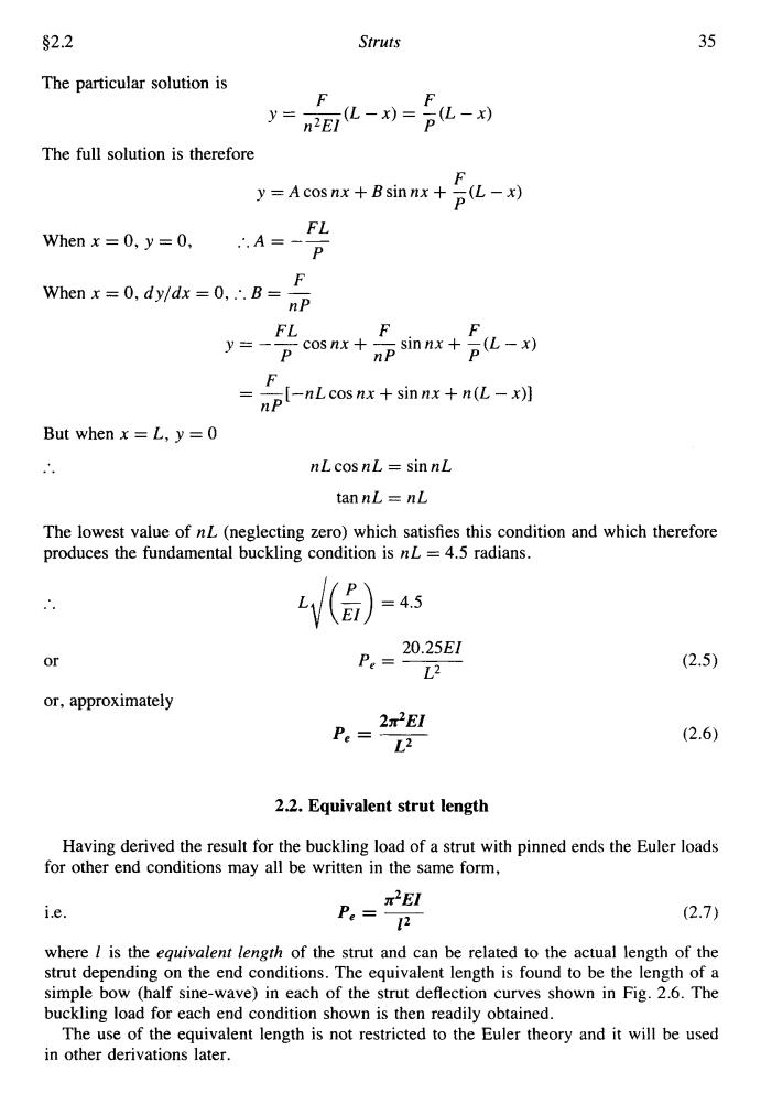
$2.2 Struts 35 The particular solution is F y-, 化-0=p化- 2EI The full solution is therefore F y=Acosnx+Bsinnx+(L-x) FL Whenx=0,y=0, ∴,A=一 P F When x=0,dy/dx=0,.'.B= nP cosnx+ FL F npsinnx+pL-划 F = np-nL cosnx+sinnx+n亿-x划 But when x=L,y=0 nL cos nL sin nL tan nL nL The lowest value of nL(neglecting zero)which satisfies this condition and which therefore produces the fundamental buckling condition is nL =4.5 radians. =45 20.25EI or P.= (2.5) L2 or,approximately 2r2E1 P.= (2.6) 2.2.Equivalent strut length Having derived the result for the buckling load of a strut with pinned ends the Euler loads for other end conditions may all be written in the same form, π2E1 i.e. P= (2.7) 12 where I is the equivalent length of the strut and can be related to the actual length of the strut depending on the end conditions.The equivalent length is found to be the length of a simple bow (half sine-wave)in each of the strut deflection curves shown in Fig.2.6.The buckling load for each end condition shown is then readily obtained. The use of the equivalent length is not restricted to the Euler theory and it will be used in other derivations later
92.2 Struts 35 The uarticular solution is F F n2EI P y=- (L-x)=-(L-x) The full solution is therefore F P y = Acosnx + Bsinnx + -(L - x) FL P When x = 0, y = 0, .A=-- .. F When x = 0, dyldx = 0, :. B = - nP F. F osnx + - sinnx + -(L - x) FL y=--c P nP P F nP = -[-nL cos nx + sin nx + n (L - x>I But when x = L, y = 0 .. nL cos nL = sin nL tannL = nL The lowest value of nL (neglecting zero) which satisfies this condition and which therefore produces the fundamental buckling condition is nL = 4.5 radians. or 20.25EI P, = ~ L* or, approximately 2.2. Equivalent strut length Having derived the result for the buckling load of a strut with pinned ends the Euler loads for other end conditions may all be written in the same form, i.e. X~EI P, = - 12 (2.7) where 1 is the equivalent length of the strut and can be related to the actual length of the strut depending on the end conditions. The equivalent length is found to be the length of a simple bow (half sine-wave) in each of the strut deflection curves shown in Fig. 2.6. The buckling load for each end condition shown is then readily obtained. The use of the equivalent length is not restricted to the Euler theory and it will be used in other derivations later
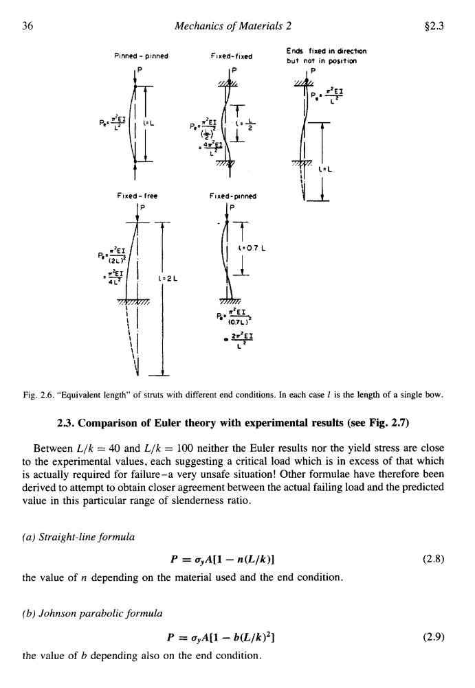
36 Mechanics of Materials 2 $2.3 Pinned-pinned Fixed-fixed Ends fixed in direction but not in position P 4m1 Fixed-free Fixed-pinned 2L7 777 70P历 R:E红 f07L)2 22虹 L Fig.2.6."Equivalent length"of struts with different end conditions.In each case is the length of a single bow. 2.3.Comparison of Euler theory with experimental results (see Fig.2.7) Between L/k =40 and L/k 100 neither the Euler results nor the yield stress are close to the experimental values,each suggesting a critical load which is in excess of that which is actually required for failure-a very unsafe situation!Other formulae have therefore been derived to attempt to obtain closer agreement between the actual failing load and the predicted value in this particular range of slenderness ratio. (a)Straight-line formula P dyA[1 n(L/k)] (2.8) the value of n depending on the material used and the end condition. (b)Johnson parabolic formula P=o,A[1-b(L/k)2] (2.9) the value of b depending also on the end condition
36 Mechanics of Materials 2 $2.3 Pinned - pinned P pe*+[ T 1 fixed-free IP fixed- fixed IP f ixed-pinned P b7 L Ends fixed in &reclan but not in position Fig. 2.6. “Equivalent length” of struts with different end conditions. In each case 1 is the length of a single bow. 23. Comparison of Euler theory with experimental results (see Fig. 2.7) Between L/k = 40 and L/k = 100 neither the Euler results nor the yield stress are close to the experimental values, each suggesting a critical load which is in excess of that which is actually required for failure-a very unsafe situation! Other formulae have therefore been derived to attempt to obtain closer agreement between the actual failing load and the predicted value in this particular range of slenderness ratio. (a) Straight-line formula P = cYA[1 - n(L/k)] the value of n depending on the material used and the end condition. (b) Johnson parabolic formula P = uyA[l - b(L/k)’] the value of b depending also on the end condition. (2.9)

$2.4 Struts 37 Neither of the above formulae proved to be very successful,and they were replaced by: (c)Rankine-Gordon formula 11.1 PR=P.+Pe (2.10) where Pe is the Euler buckling load and Pe is the crushing(compressive yield)load =oA. This formula has been widely used and is discussed fully in $2.5. 2.4.Euler "validity limit" From the graph of Fig.2.7 and the comments above,it is evident that the Euler theory is unsafe for small L/k ratios.It is useful,therefore,to determine the limiting value of L/k below which the Euler theory should not be applied;this is termed the validity limit. Euler curve For structural steel,curves coincide at L/k.B0 6 Yieid or collapse stress ssaus ayor de Experimem al results Curves coincide at L/k:120 50 100 150 Slenderness rotio L/k Fig.2.7.Comparison of experimental results with Euler curve. The validity limit is taken to be the point where the Euler oe equals the yield or crushing stress oy,i.e.the point where the strut load P=A Now the Euler load can be written in the form CTEl-CTEAR Pe=C"L2 L where C is a constant depending on the end condition of the strut. Therefore in the limiting condition A=CTEAk2 L2
$2.4 Struts 37 Neither of the above formulae proved to be very successful, and they were replaced by: (c) Rankine-Gordon formula (2.10) where P, is the Euler buckling load and P, is the crushing (compressive yield) load = a,A. This formula has been widely used and is discussed fully in $2.5. 2.4. Euler "validity limit" From the graph of Fig. 2.7 and the comments above, it is evident that the Euler theory is unsafe for small L/k ratios. It is useful, therefore, to determine the limiting value of L/k below which the Euler theory should not be applied; this is termed the validity limit. Eukr curve Yield or colbpse stress Curves coincide at L/k*120 1 50 100 150 Slenderness ratio L/k Fig. 2.7. Comparison of experimental results with Euler curve. The validity limit is taken to be the point where the Euler a, equals the yield or crushing stress ay, i.e. the point where the strut load P = ayA Now the Euler load can be written in the form where C is a constant depending on the end condition of the strut. Therefore in the limiting condition n2EAk2 L2 aVA = C------