CHAPTER 9 THIN CYLINDERS AND SHELLS Summary The stresses set up in the walls of a thin cylinder owing to an internal pressure p are: circumferential or hoop stress o#= pd 2t pd longitudinal or axial stress 4t where d is the internal diameter and t is the wall thickness of the cylinder. Then: longitudinal strain ELGL-van] hoop strain & ELon-vaL] change of interal volume of cylinder under pressurep 4E[5-4p]r change of volume of contained liquid under pressure- pV K where K is the bulk modulus of the liquid. For thin rotating cylinders of mean radius R the tensile hoop stress set up when rotating at ωrad/s is given by H=p02R2. For thin spheres: cirumferentialor hoop stressd 4t change of volume under pressure 3pd 4E1-y Effects of end plates and joints-add "joint efficiency factor"n to denominator of stress equations above. 9.1.Thin cylinders under internal pressure When a thin-walled cylinder is subjected to internal pressure,three mutually perpendicular principal stresses will be set up in the cylinder material,namely the circumferential or hoop 198
CHAPTER 9 THIN CYLINDERS AND SHELLS Summary The stresses set up in the walls of a thin cylinder owing to an internal pressure p are: circumferential or hmp stress aH = Pd Pd longitudinal or axial stress aL = - 4t where d is the internal diameter and t is the wall thickness of the cylinder. longitudinal strain cL = - [aL - VaH] 1 E 1 E Then: hoop strain cH = - [aH - vaL] Fd 4tE PV change of volume of contained liquid under pressure = - K change of internal volume of cylinder under pressure = - [ 5 - 4v] V where K is the bulk modulus of the liquid. For thin rotating cylinders of mean radius R the tensile hoop stress set up when rotating at For thin spheres: w rad/s is given by GH = po2R2. Pd circumferential or hoop stress aH = - 4t 3Pd change of volume under pressure = - [ 1 - v] V 4tE Eflects of end plates and joints-add “joint efficiency factor” ‘1 to denominator of stress equations above. 9.1. Thin cylinders under internal pressure When a thin-walled cylinder is subjected to internal pressure, three mutually perpendicular principal stresses will be set up in the cylinder material, namely the circumferential or hoop 198
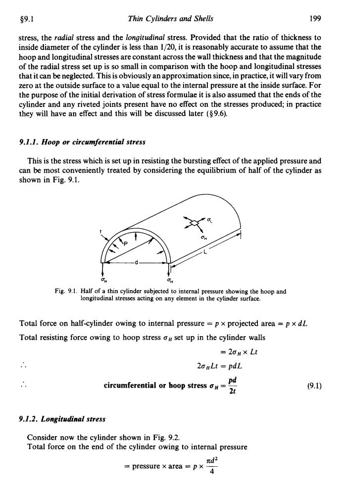
s9.1 Thin Cylinders and Shells 199 stress,the radial stress and the longitudinal stress.Provided that the ratio of thickness to inside diameter of the cylinder is less than 1/20,it is reasonably accurate to assume that the hoop and longitudinal stresses are constant across the wall thickness and that the magnitude of the radial stress set up is so small in comparison with the hoop and longitudinal stresses that it can be neglected.This is obviously an approximation since,in practice,it will vary from zero at the outside surface to a value equal to the internal pressure at the inside surface.For the purpose of the initial derivation of stress formulae it is also assumed that the ends of the cylinder and any riveted joints present have no effect on the stresses produced;in practice they will have an effect and this will be discussed later ($9.6). 9.1.1.Hoop or circumferential stress This is the stress which is set up in resisting the bursting effect of the applied pressure and can be most conveniently treated by considering the equilibrium of half of the cylinder as shown in Fig.9.1. CH 60 Fig.9.1.Half of a thin cylinder subjected to internal pressure showing the hoop and longitudinal stresses acting on any element in the cylinder surface. Total force on half-cylinder owing to internal pressure p x projected area =p x dL Total resisting force owing to hoop stress aH set up in the cylinder walls =2oH×Lt 20HLt pdL circumferential or hoop stress o#= pd 2t (9.1) 9.1.2.Longitudinal stress Consider now the cylinder shown in Fig.9.2. Total force on the end of the cylinder owing to internal pressure nd2 pressure x area=px4
59.1 Thin Cylinders and Shells 199 stress, the radial stress and the longitudinal stress. Provided that the ratio of thickness to inside diameter of the cylinder is less than 1/20, it is reasonably accurate to assume that the hoop and longitudinal stresses are constant across the wall thickness and that the magnitude of the radial stress set up is so small in comparison with the hoop and longitudinal stresses that it can be neglected. This is obviously an approximation since, in practice, it will vary from zero at the outside surface to a value equal to the internal pressure at the inside surface. For the purpose of the initial derivation of stress formulae it is also assumed that the ends of the cylinder and any riveted joints present have no effect on the stresses produced; in practice they will have an effect and this will be discussed later (5 9.6). 9.1.1. Hoop or circumferential stress This is the stress which is set up in resisting the bursting effect of the applied pressure and can be most conveniently treated by considering the equilibrium of half of the cylinder as shown in Fig. 9.1. QU Qn Fig. 9.1. Half of a thin cylinder subjected to internal pressure showing the hoop and longitudinal stresses acting on any element in the cylinder surface. Total force on half-cylinder owing to internal pressure = p x projected area = p x dL Total resisting force owing to hoop stress on set up in the cylinder walls = 2oH x Lt .. 2aHLt = pdL Pd .. circumferential or hoop stress uH = - 2t 9.1.2. Longitudinal stress Consider now the cylinder shown in Fig. 9.2. Total force on the end of the cylinder owing to internal pressure nd2 = pressure x area = p x ~ 4
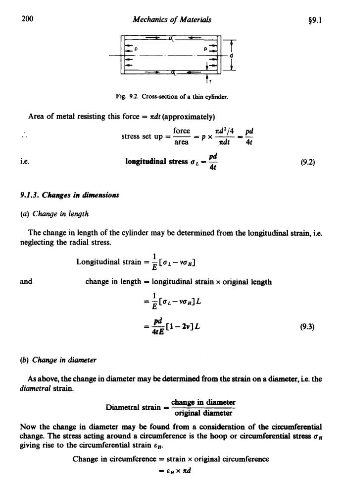
200 Mechanics of Materials $9.1 Fig.9.2.Cross-section of a thin cylinder. Area of metal resisting this force ndt(approximately) force nd2/4 pd stress set up =卫X area 元dt4t i.e. Pd longitudinal stress o= (9.2) 4t 9.1.3.Changes in dimensions (a)Change in length The change in length of the cylinder may be determined from the longitudinal strain,i.e. neglecting the radial stress. Longitudinal strain-E[-vo and change in length longitudinal strain x original length 1 -EloL-vOm]L -是1-2 (9.3) (b)Change in diameter As above,the change in diameter may be determined from the strain on a diameter,i.e.the diametral strain. Diametral strain change in diameter original diameter Now the change in diameter may be found from a consideration of the circumferential change.The stress acting around a circumference is the hoop or circumferential stress o# giving rise to the circumferential strain Change in circumference strain x original circumference =eH×元d
200 Mechanics of Materials 09.1 Fig. 9.2. Cross-section of a thin cylinder. Area of metal resisting this force = ltdt(approximate1y) .. i.e. force d2/4 pd stress set up = - = p x - = - area ndt 4t pd longitudinal stress uL = - 4t 9.1.3. Changes in dinrensions (a) Change in length The change in length of the cylinder may be determined from the longitudinal strain, i.e. neglecting the radial stress. 1 E Longitudinal strain = - [uL - vuH] and change in length = longitudinal strain x original length 1 E = -[uL-vuH]L pd =-[1-2v]L 4tE (b) Change in diameter (9.3) As above, the change in diameter may be determined from the strain on a diameter, i.e. the diametral strain. change in diameter original diameter Diametral strain = Now the change in diameter may be found from a consideration of the cipcumferential change. The stress acting around a circumference is the hoop or circumferential stress on giving rise to the circumferential strain cH. Change in circumference = strain x original circumference =EHXnd
s9.2 Thin Cylinders and Shells 201 New circumference nd+nde# =d(1+eH) But this is the circumference of a circle of diameter d(1+8#) New diameter =d(1+) Change in diameter dem d起班一H Diametral strainod i.e. the diametral strain equals the hoop or circumferential strain (94) d。 Thus change in diameterden-[v E2-] (9.5) (c)Change in internal volume Change in volume volumetric strain x original volume From the work of§14.5,page364. volumetric strain sum of three mutually perpendicular direct strains 8L+26D 1 2 =ELoL-vom]+ECon-voL] 1 =E[oL+20-v(on+201)] pd1+4-v2+2] 5-4幻 Therefore with original internal volume V change in internal volumep 4E5-4n]y (9.6) 9.2.Thin rotating ring or cylinder Consider a thin ring or cylinder as shown in Fig.9.3 subjected to a radial pressure p caused by the centrifugal effect of its own mass when rotating.The centrifugal effect on a unit length
$9.2 Thin Cylinders and Sheh 201 New circumference = xd + 7cd~ H = d(1 +EH) But this is the circumference of a circle of diameter d (1 +E,,) .. .. New diameter = d (1 + E~) Change in diameter = dEH d&H Diametral strain E,, = - = eH the diametral strain equals the hoop or circumferential strain d i.e. (9.4) d E Thus change in diameter = deH = - [aH - voL] Pd’ = ---[2-v] 4tE (c) Change in internal volume Change in volume = volumetric strain x original volume From the work of $14.5, page 364. volumetric strain = sum of three mutually perpendicular direct strains = EL+ 2ED 1 E = -[UL+2aH-v(aH+2aL)J = -[ Pd 1 +4-v(2+2) J 4tE Pd = -[5-4v] 4t E Therefore with original internal volume V Pd cbange in internal volume = - [5 - 4v] Y 4tE 9.2. Thin rotating ring or cylinder (9.5) Consider a thin ring or cylinder as shown in Fig. 9.3 subjected to a radial pressure p caused by the centrifugal effect of its own mass when rotating. The centrifugal effect on a unit length
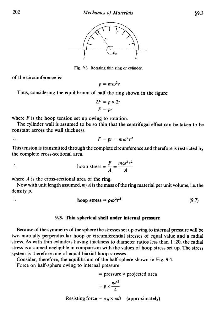
202 Mechanics of Materials §9.3 Fig.9.3.Rotating thin ring or cylinder. of the circumference is: p=mω2r Thus,considering the equilibrium of half the ring shown in the figure: 2F=p×2r F=pr where F is the hoop tension set up owing to rotation. The cylinder wall is assumed to be so thin that the centrifugal effect can be taken to be constant across the wall thickness. F=pr =mo2r2 This tension is transmitted through the complete circumference and therefore is restricted by the complete cross-sectional area. hoop stress F mo2r2 AA where A is the cross-sectional area of the ring. Now with unit length assumed,m/A is the mass of the ring material per unit volume,i.e.the density p. hoop stress =po2r2 (9.7) 9.3.Thin spherical shell under internal pressure Because of the symmetry of the sphere the stresses set up owing to internal pressure will be two mutually perpendicular hoop or circumferential stresses of equal value and a radial stress.As with thin cylinders having thickness to diameter ratios less than 1:20,the radial stress is assumed negligible in comparison with the values of hoop stress set up.The stress system is therefore one of equal biaxial hoop stresses. Consider,therefore,the equilibrium of the half-sphere shown in Fig.9.4. Force on half-sphere owing to internal pressure pressure x projected area nd2 =卫X 4 Resisting force =#x ndt (approximately)
202 Mechanics of Materials $9.3 F F Fig. 9.3. Rotating thin ring or cylinder. of the circumference is: p = mo2r Thus, considering the equilibrium of half the ring shown in the figure: 2F=px2r F = pr where F is the hoop tension set up owing to rotation. constant across the wall thickness. .. This tension is transmitted through the complete circumference and therefore is restricted by the complete cross-sectional area. The cylinder wall is assumed to be so thin that the centrifugal effect can be taken to be F = pr = mo2r2 where A is the cross-sectional area of the ring. density p. Now with unit length assumed, m/A is the mass of the ring material per unit volume, i.e. the .. hoop stress = po2r2 (9.7) 9.3. Thin spherical shell under internal pressure Because of the symmetry of the sphere the stresses set up owing to internal pressure will be two mutually perpendicular hoop or circumferential stresses of equal value and a radial stress. As with thin cylinders having thickness to diameter ratios less than 1 : 20, the radial stress is assumed negligible in comparison with the values of hoop stress set up. The stress system is therefore one of equal biaxial hoop stresses. Consider, therefore, the equilibrium of the half-sphere shown in Fig. 9.4. Force on half-sphere owing to internal pressure = pressure x projected area nd2 =px4 Resisting force = oH x ltdt (approximately)
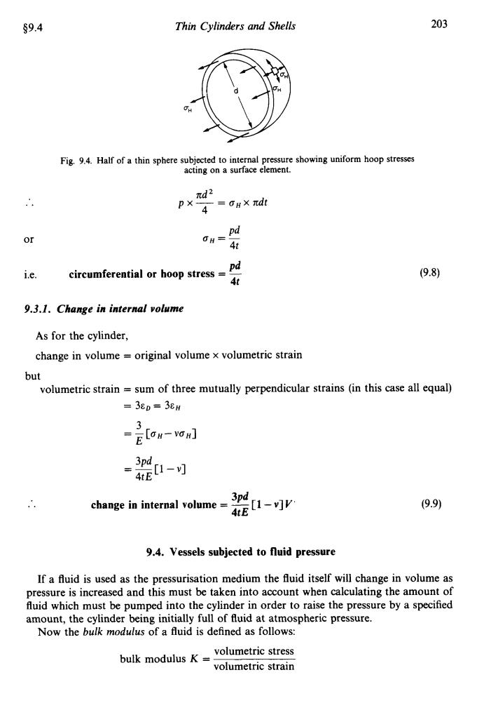
$9.4 Thin Cylinders and Shells 203 Fig.9.4.Half of a thin sphere subjected to internal pressure showing uniform hoop stresses acting on a surface element. nd2 px 4=0HXπd or 0H= Pd 4t pd i.e. circumferential or hoop stress (9.8) 4t 9.3.1.Change in internal volume As for the cylinder, change in volume original volume x volumetric strain but volumetric strain sum of three mutually perpendicular strains (in this case all equal) =38p=38H 3 =EoH-G小 -- change in internal volume= 3pd [1-v]v (9.9) 9.4.Vessels subjected to fluid pressure If a fluid is used as the pressurisation medium the fluid itself will change in volume as pressure is increased and this must be taken into account when calculating the amount of fluid which must be pumped into the cylinder in order to raise the pressure by a specified amount,the cylinder being initially full of fluid at atmospheric pressure. Now the bulk modulus of a fluid is defined as follows: bulk modulusK=volumetric stress volumetric strain
59.4 Thin Cylinders and Shells 203 .. or Fig. 9.4. Half of a thin sphere subjected to internal pressure showing uniform hoop stresses acting on a surface element. nd 4 p x - = CTH x ndt Pd bH=- 4t Pd circumferential or hoop stress = - 4t i.e. 9.3.1. Change in internal volume As for the cylinder, change in volume = original volume x volumetric strain but volumetric strain = sum of three mutually perpendicular strains (in this case all equal) = 3ED = 3EH .. 3Pd change in internal volume = - [ 1 - v] Y 4tE (9.9) 9.4. Vessels subjected to fluid pressure If a fluid is used as the pressurisation medium the fluid itself will change in volume as pressure is increased and this must be taken into account when calculating the amount of fluid which must be pumped into the cylinder in order to raise the pressure by a specified amount, the cylinder being initially full of fluid at atmospheric pressure. Now the bulk modulus of a fluid is defined as follows: volumetric stress volumetric strain bulk modulus K =
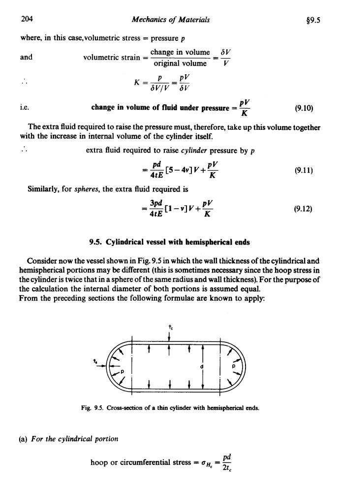
204 Mechanics of Materials s9.5 where,in this case,volumetric stress pressure p and volumetric strain change in volumeδV original volume p pV K-玩-影 i.e. change in volume of fluid under pressure= pV K (9.10) The extra fluid required to raise the pressure must,therefore,take up this volume together with the increase in internal volume of the cylinder itself. extra fluid required to raise cylinder pressure by p 证5-物+义 (9.11) Similarly,for spheres,the extra fluid required is [1-v]v+PY 3pd (9.12) 9.5.Cylindrical vessel with hemispherical ends Consider now the vessel shown in Fig.9.5 in which the wall thickness of the cylindrical and hemispherical portions may be different(this is sometimes necessary since the hoop stress in the cylinder is twice that in a sphere of the same radius and wall thickness).For the purpose of the calculation the internal diameter of both portions is assumed equal. From the preceding sections the following formulae are known to apply: Fig.9.5.Cross-section of a thin cylinder with hemispherical ends. (a)For the cylindrical portion pd hoop or circumferential stresst
204 Mechanics of Materials 59.5 where, in this case,volumetric stress = pressure p and volumetric strain = - change in volume 6V original volume Y -_ (9.10) PV i.e. change in volume of fluid under pressure = - K The extra fluid required to raise the pressure must, therefore, take up this volume together with the increase in internal volume of the cylinder itself. .. extra fluid required to raise cylinder pressure by p = -[5-4v] Pd v+- PV 4tE K Similarly, for spheres, the extra fluid required is = ~ 3Pd [l - v] v+ PV - 4tE K (9.1 1) (9.12) 9.5. Cylindrical vessel with hemispherical ends Consider now the vessel shown in Fig. 9.5 in which the wall thickness of the cylindrical and hemispherical portions may be different (this is sometimes necessary since the hoop stress in the cylinder is twice that in a sphere of the same radius and wall thickness). For the purpose of the calculation the internal diameter of both portions is assumed equal. From the preceding sections the following formulae are known to apply: I c 1 I t t t I I I I 1 I Fig. 9.5. Cross-section of a thin cylinder with hemispherical ends. (a) For the cylindrical portion Pd 2tc hoop or circumferential stress = bHc = -
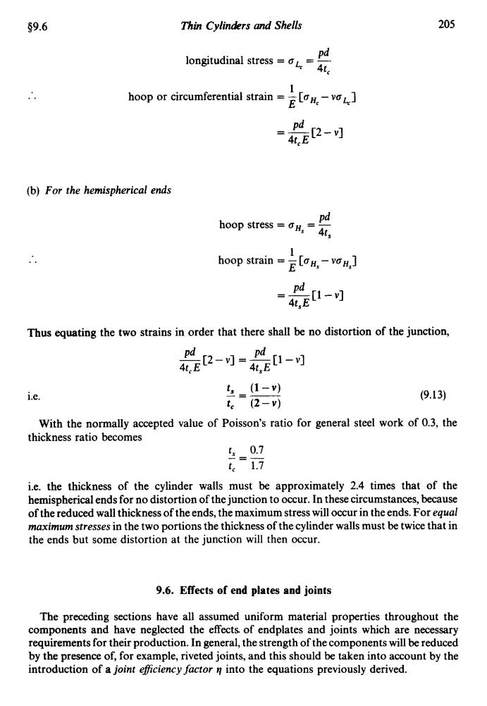
$9.6 Thin Cylinders and Shells 205 longitudinal stress=L= pd Ate 1 hoop or circumferential strain 2- pd = (b)For the hemispherical ends pd hoop stress=6H,=4在, 1 hoop strain=v 、pd [1- 4t E Thus equating the two strains in order that there shall be no distortion of the junction, 卫--是-可 pd i.e. 5=1-) (9.13) t.(2-v) With the normally accepted value of Poisson's ratio for general steel work of 0.3,the thickness ratio becomes t1.7 i.e.the thickness of the cylinder walls must be approximately 2.4 times that of the hemispherical ends for no distortion of the junction to occur.In these circumstances,because of the reduced wall thickness of the ends,the maximum stress will occur in the ends.For equal maximum stresses in the two portions the thickness of the cylinder walls must be twice that in the ends but some distortion at the junction will then occur. 9.6.Effects of end plates and joints The preceding sections have all assumed uniform material properties throughout the components and have neglected the effects.of endplates and joints which are necessary requirements for their production.In general,the strength of the components will be reduced by the presence of,for example,riveted joints,and this should be taken into account by the introduction of a joint efficiency factor n into the equations previously derived
$9.6 Thin Cylinders and Shells 205 .. Pd longitudinal stress = aLc = - 44 1 E hoop or circumferential strain = - [gHc - vak] Pd = -[2-v] 44 E (b) For the hemispherical ends Pd 4ts hoop stress = oHs = - 1 E hoop strain = - [aHs - voHs] Pd = -[1 -v] 4t,E Thus equating the two strains in order that there shall be no distortion of the junction, -[2-v] Pd = -[1 Pd -v] 4t, E 4t,E i.e. (9.13) With the normally accepted value of Poisson’s ratio for general steel work of 0.3, the t, 0.7 t, 1.7 thickness ratio becomes - =- i.e. the thickness of the cylinder walls must be approximately 2.4 times that of the hemispherical ends for no distortion of the junction to occur. In these circumstances, because of the reduced wall thickness of the ends, the maximum stress will occur in the ends. For equal maximum stresses in the two portions the thickness of the cylinder walls must be twice that in the ends but some distortion at the junction will then occur. 9.6. Effects of end plates and joints The preceding sections have all assumed uniform material properties throughout the components and have neglected the effects of endplates and joints which are necessary requirements for their production. In general, the strength of the components will be reduced by the presence of, for example, riveted joints, and this should be taken into account by the introduction of a joint eficiency factor tf into the equations previously derived
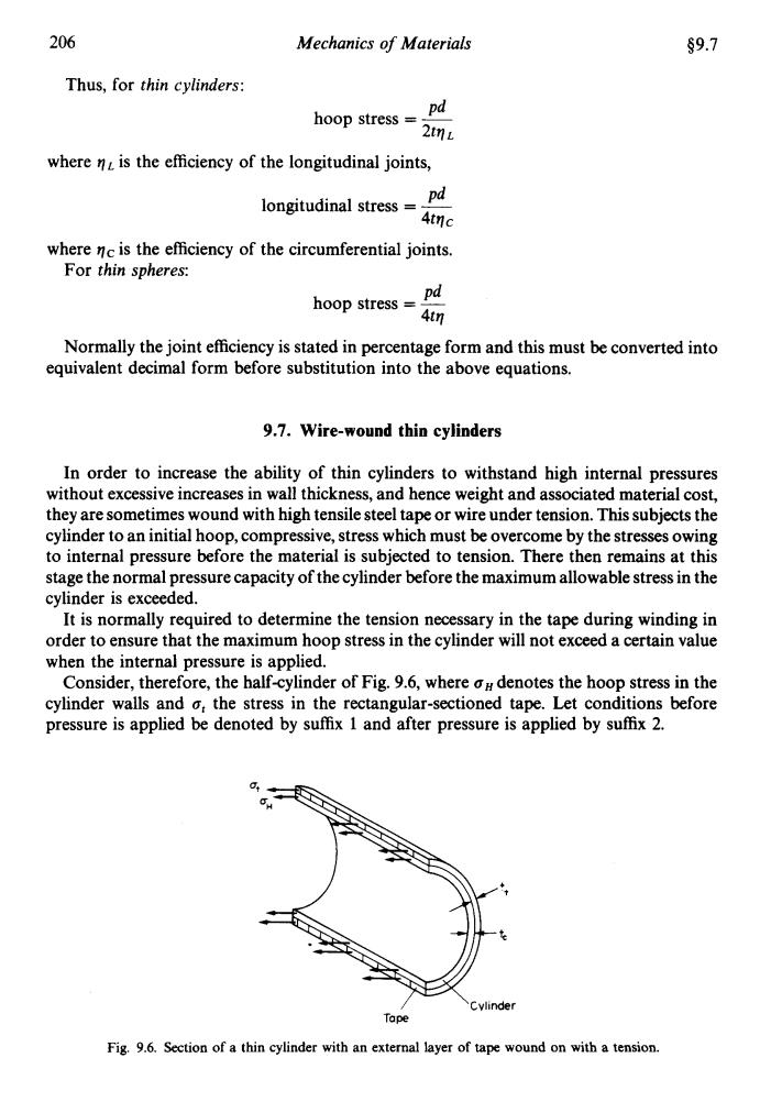
206 Mechanics of Materials 9.7 Thus,for thin cylinders: pd hoop stress 2tnL where n is the efficiency of the longitudinal joints, pd longitudinal stress Atnc where nc is the efficiency of the circumferential joints. For thin spheres: hoop stress pd 4tn Normally the joint efficiency is stated in percentage form and this must be converted into equivalent decimal form before substitution into the above equations. 9.7.Wire-wound thin cylinders In order to increase the ability of thin cylinders to withstand high internal pressures without excessive increases in wall thickness,and hence weight and associated material cost, they are sometimes wound with high tensile steel tape or wire under tension.This subjects the cylinder to an initial hoop,compressive,stress which must be overcome by the stresses owing to internal pressure before the material is subjected to tension.There then remains at this stage the normal pressure capacity of the cylinder before the maximum allowable stress in the cylinder is exceeded. It is normally required to determine the tension necessary in the tape during winding in order to ensure that the maximum hoop stress in the cylinder will not exceed a certain value when the internal pressure is applied. Consider,therefore,the half-cylinder of Fig.9.6,where o#denotes the hoop stress in the cylinder walls and o,the stress in the rectangular-sectioned tape.Let conditions before pressure is applied be denoted by suffix 1 and after pressure is applied by suffix 2. 0 Cylinder Tape Fig.9.6.Section of a thin cylinder with an external layer of tape wound on with a tension
206 Mechanics of Materials 59.7 Thus, for thin cylinders: Pd 2tq L hoop stress = ~ where q is the efficiency of the longitudinal joints, Pd longitudinal stress = - 4tqc where qc is the efficiency of the circumferential joints. For thin spheres: Pd hoop stress = - 4tV Normally the joint efficiency is stated in percentage form and this must be converted into equivalent decimal form before substitution into the above equations. 9.7. Wire-wound thin cylinders In order to increase the ability of thin cylinders to withstand high internal pressures without excessive increases in wall thickness, and hence weight and associated material cost, they are sometimes wound with high tensile steel tape or wire under tension. This subjects the cylinder to an initial hoop, compressive, stress which must be overcome by the stresses owing to internal pressure before the material is subjected to tension. There then remains at this stage the normal pressure capacity of the cylinder before the maximum allowable stress in the cylinder is exceeded. It is normally required to determine the tension necessary in the tape during winding in order to ensure that the maximum hoop stress in the cylinder will not exceed a certain value when the internal pressure is applied. Consider, therefore, the half-cylinder of Fig. 9.6, where oH denotes the hoop stress in the cylinder walls and o, the stress in the rectangular-sectioned tape. Let conditions before pressure is applied be denoted by suffix 1 and after pressure is applied by suffix 2. Fig. 9.6. Section ofa Tope thin cylinder with an external layer of tape wound on with a tension

$9.7 Thin Cylinders and Shells 207 Now force owing to tape =o x area =06,×2L resistive force in the cylinder material=x 2Lt i.e.for equilibrium ,×2Lt,=0H,×2Lt or 0t,Xt,=oH,×te so that the compressive hoop stress set up in the cylinder walls after winding and before pressurisation is given by (compressive) (9.14) t This equation will be modified if wire of circular cross-section is used for the winding process in preference to rectangular-sectioned tape.The area carrying the stress a,.will then be 2na where a is the cross-sectional area of the wire and n is the number of turns along the cylinder length. After pressure has been applied another force is introduced pressure x projected area pdL Again,equating forces for equilibrium of the half-cylinder, pdL=(oH,×2Lt)+(o,×2Lt) (9.15) where,is the hoop stress in the cylinder after pressurisation and is the final stress in the tape after pressurisation. Since the limiting value of o,is known for any given internal pressure p,this equation yields the value of Now the change in strain on the outside surface of the cylinder must equal that on the inside surface of the tape if they are to remain in contact. Change in strain in the tape E where E,is Young's modulus of the tape. In the absence of any internal pressure originally there will be no longitudinal stress or strain so that the original strain in the cylinder walls is given byo/E,where E is Young's modulus of the cylinder material.When pressurised,however,the cylinder will be subjected to a longitudinal strain so that the final strain in the cylinder walls is given by 1 1「 d 。 change in strain on the cylinder E.1om-v 4t: 一OH 1 1「 pa Thus with o obtained in terms of a from eqn.(9.14),p and o known,and o found from eqn.(9.15)the only unknown at,can be determined
$9.7 Thin Cylinders and Shells 207 Now force owing to tape = or] x area = ut, x 2Lt, ut, x 2Lt, = OH, x 2Ltc bt x t, = OH] x t, resistive force in the cylinder material = oH, x 2Lt, i.e. for equilibrium or so that the compressive hoop stress set up in the cylinder walls after winding and before pressurisation is given by t o,,, = crl x 2 (compressive) (9.14) tc This equation will be modified if wire of circular cross-section is used for the winding process in preference to rectangular-sectioned tape. The area carrying the stress ctl will then beans where a is the cross-sectional area of the wire and n is the number of turns along the cylinder length. After pressure has been applied another force is introduced = pressure x projected area = pdL Again, equating forces for equilibrium of the halfcylinder, pdL = (oH, x 2Ltc) + (or, x 2Lt,) where o,,, is the hoop stress in the cylinder after pressurisation and otl is the final stress in the tape after pressurisation. Since the limiting value of (iH, is known for any given internal pressure p, this equation yields the value of or,. Now the change in strain on the outside surface of the cylinder must equal that on the inside surface of the tape if they are to remain in contact. (9.15) or, - or1 Change in strain in the tape = ~ Et where E, is Young’s modulus of the tape. In the absence of any internal pressure originally there will be no longitudinal stress or strain so that the original strain in the cylinder walls is given by oHl/Ec, where E, is Young’s modulus of the cylinder material. When pressurised, however, the cylinder will be subjected to a longitudinal strain so that the final strain in the cylinder walls is given by .. change in strain on the cylinder = Thus with bH, obtained in terms of err, from eqn. (9.14), p and bH, known, and or, found from eqn. (9.15) the only unknown or, can be determined