s 3776. 1965. posite materials.AFML-TR-67-423. 31.Halpin,J.C.and Tsai,S.W.1969.Effects of environmental factors on com- proved bounds on effective properties.Applied Mechanics Reviews,44(2), Torquato,S.1991.Random heterogeneous media:microstructure and im- materials.Journal of Applied Mechanics,31,223-232.Errata,p.219 (March 29.Hashin,Z.and Rosen,B.W.1964.The elastic moduli of fiber reinforced actions of AIME,218,36-41. 28.Paul,B.1960.Prediction of elastic constants of multi-phase materials.Trans- cells.Applied Mechanics Reviews,42(7),193-221. Aboudi,J.1989.Micromechanical analysis of composites by the method of Principles of Composite Material Mechanics 1 Lamina the effective strengths s),s,s,and s and the corresponding values of the volume-averaged stresses that cause failure of the lamina under these same simple states of stress.The stress-strain curves in figure 4.1 show the graphical interpretation of these simple states of stress, approach,the"effective strengths"of the lamina may be defined as ultimate associated with the lamina principal material axes.Using a similar ina stresses to the volume-averaged lamina strains [recall equation(2.7)to equation (2.9)1,are defined by simple uniaxial or shear stress conditions tive moduli."The effective moduli,which relate the volume-averaged lam- relationships for the orthotropic lamina are simplified by the use of"effec- Interlaminar strengths will be discussed in chapter 7 and chapter 9. As shown in chapters 2 and chapter 3,the linear elastic stress-strain as are several micromechanical models for predicting the lamina strengths. strengths under off-axis or multiaxial loading are discussed in this chapter, TThe relationships among these five lamina strengths and the allowable lamina lamina strengths form the basis of a simplified lamina strength analysis, which will,in turn,be used later in a simplified laminate strength analysis. the principal material axes is still another independent property.These five that will be explained later.The in-plane shear strength sr associated with the corresponding tensile strengths s)and,s),and the transverse tensile strength s is typically the smallest of all the lamina strengths for reasons strengths s)and s,associated with these directions may be different from greater than the transverse strength,s In addition,the compressive longitudinal strength of the continuous fiber-reinforced lamina,s,is much chapter 1,the strength of a composite is derived from the strength of the fibers,but this strength is highly directional in nature.For example,the analysis of composite strength is more difficult than the analysis of elastic behavior,which was discussed in chapter 2 and chapter 3.As shown in Because of the variety of failure modes that can occur in composites,the Introduction Strength of a Continuous Fiber-Reinforced
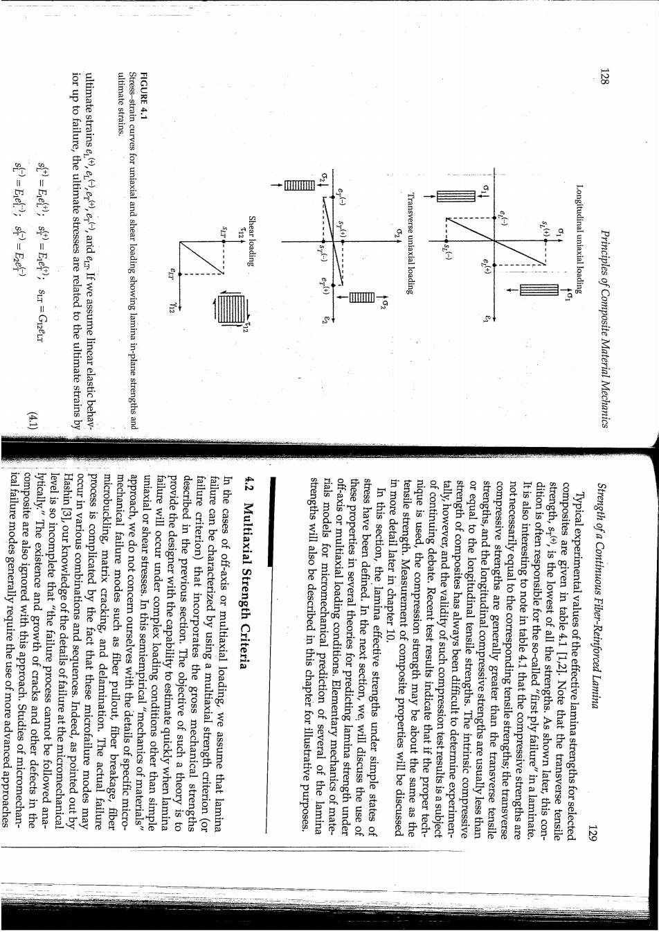
ultimate strains. FIGURE 4.1 oD.号号 ior up to failure,the ultimate stresses are related to the ultimate strains by ultimate strains e,e,e),arid er If we assume linear elastic behav- Stress-strain curves for uniaxial and shear loading showing lamina in-plane strengths and W 9 Shear loading Longitudinal uniaxial loading Principles of Composite Material Mechanics composite are also ignored with this approach.Studies of micromechan- ical failure modes generally require the use of more advanced approaches lytically."The existence and growth of cracks and other defects in the Hashin [3],our knowledge of the details of failure at the micromechanical level is so incomplete that "the failure process cannot be followed ana- microbuckling,matrix cracking,and delamination.The actual failure process is complicated by the fact that these microfailure modes may occur in various combinations and sequences.Indeed,as pointed out by mechanical failure modes such as fiber pullout,fiber breakage,fiber approach,we do not concern ourselves with the details of specific micro- uniaxial or shear stresses.In this semiempirical"mechanics of materials" failure will occur under complex loading conditions other than simple described in the previous section.The objective of such a theory is to provide the designer with the capability to estimate quickly when lamina failure criterion)that incorporates the gross mechanical strengths In the cases of off-axis or multiaxial loading,we assume that lamina failure can be characterized by using a multiaxial strength criterion (or 4.2 Multiaxial Strength Criteria rials models for micromechanical prediction of several of the lamina strengths will also be described in this chapter for illustrative purposes. off-axis or multiaxial loading conditions.Elementary mechanics of mate- stress have been defined.In the next section,we,will discuss the use of these properties in several theories for predicting lamina strength under In this section,the lamina effective strengths under simple states of in more detail later in chapter 10. nique is used,the compression strength may be about the same as the tensile strength.Measurement of composite properties will be discussed of continuing debate.Recent test results indicate that if the proper tech- tally,however,and the validity of such compression test results is a subject strength of composites has always been difficult to determine experimen- or equal to the longitudinal tensile strengths.The intrinsic compressive strengths,and the longitudinal compressive strengths are usually less than not necessarily equal to the corresponding tensile strengths;the transverse compressive strengths are generally greater than the transverse tensile It is also interesting to note in table 4.1 that the compressive strengths are strength,s(),is the lowest of all the strengths.As shown later,this con- dition is often responsible for the so-called"first ply failure"in a laminate. composites are given in table 4.1 [1,2].Note that the transverse tensile Typical experimental values of the effective lamina strengths for selected Strength of a Continuous Fiber-Reinforced Lamina 三
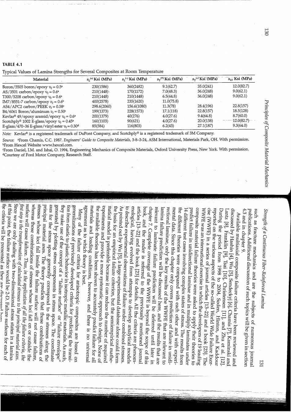
TABLE 4.1 Typical Values of Lamina Strengths for Several Composites at Room Temperature Material sKsi (MPa) 5LKsi (MPa) s Ksi (MPa) s(-Ksi (MPa) sir Ksi (MPa) Boron/5505 boron/epoxy v:=0.5 230(1586) 360(2482) 9.1(62.7刀 35.0(241) 12.0(82.7) AS/3501 carbon/epoxy :=0.6 210(1448) 170(1172 7.0(48.3) 36.0(248) 9.062.1) T300/5208 carbon/epoxy v:=0.6 210(1448) 210(1448) 6.5(44.8) 36.0(248) 9.0(62.1) IM7/8551-7 carbon/epoxy :=0.65 400(2578) 235(1620) 11.075.8) AS4/APC2 carbon/PEEK =0.58 298.6(2060) 156.6(1080) 11.378) 28.4(196) 22.8(157 B4/6061 Boron/aluminum v;=0.50 199(1373) 228(1573) 17.1(118) 22.8157 18.5(128) Kevlar 49/epoxy aramid/epoxy v:=0.6 200(1379) 40(276) 4.0(27.6) 94648) 8.7(60.0) Scotchply1002 E-glass/epoxy v:=0.45 160(1103) 90(621) 4.0(27.6) 20.0(138) 12:0(82.7月 E-glass/470-36 E-glass/vinyl ester0.30 85(584) 116(803) 6.2(43) 27.1(187 9.3(64.0) Note:Kevlar is a registered trademark of DuPont Company,and Scotchply is a registered trademark of 3M Company. Source:From Chamis,C.C.1987.Engineers'Guide to Composite Materials,3-8-3-24,ASM International,Materials Park,OH With permission. From Hexcel Website www.hexcel.com From Daniel,I.M.and Ishai,.1994,Engineering Mechanics of Composite Materials,Oxford University Press,New York.With permission. Courtesy of Ford Motor Company,Research Staff. Principles of Composite Material Mechanics the criteria will be presented as they are dismede at this point,the failure surface would be 2-D.Failure surfaces for each of Since we are only dealing with two-dimensional stress states in a lamina first step is the transformation of calculated stresses to the principal material axes. surface will cause failure.Thus,in the application of all the failure criteria,the stresses whose loci fall inside the failure surface will not cause failure, whereas those combinations of stresses whose loci fall on or outside the axes for the stress space generally correspond to the stresses along the principal material axes.The theory predicts that those combinations of they make use of the concept of a "failure surface"or "failure envelope" generated by plotting stress components in stress space.The coordinate tion from elastic to plastic behavior in isotropic metallic materials.As such, generalizations of previously developed criteria for predicting the transi- Many of the failure criteria for anisotropic composites are based on the available theories has been shown to accurately predict failure for all materials and loading conditions,however,and there is no universal agreement as to which theory is best. experiments and provide a more systematic approach to design.None of the basis for an empirical failure criterion,but the semiempirical mathe- matical model is preferable because it can reduce the number of required to describe experimental observations of failure under combined stresses. As pointed out by Wu [51,a large experimental database alone could form enological,having evolved from attempts to develop analytical models book,and the reader is referred to the previously mentioned journal articles [13-22]and the book [23]for details.All the criteria are phenom- chapter 7.Complete coverage of the WWFE is beyond the scope of this relevant to laminate failure prediction will be deferred until later in lamina failure prediction will be discussed here,and the results that are rectional laminae,only the key results of the WWFE that are relevant to mental data.Since this chapter only covers prediction of failure in unidi- 14 different test cases involving complex states of stress.The results from the different theories were compared with each other and with experi- predict failure in unidirectional laminae and in multiply laminates under WWFE was an international exercise in which the developers of 19 leading composite material failure theories were asked to apply their theories to cise(WWFE)in a series of journal articles [13-22]and a book [23].The During the period from 1998 to 2004,Soden,Hinton,and Kaddour reported on the various aspects of the so-called World Wide Failure Exer- discussed by Hashin [41,Wu [51,Sendeckyj [61,Chamis [7],Kaminski and Lantz [8],Franklin [9],Tsai [10],Christensen [11],and Zhu et al.[12] Available multiaxial composite failure criteria have been reviewed and 4.3 and in chapter 9. such as fracture mechanics and are the subjects of numerous journal publications.Additional discussion of such topics will be given in section Strength of a Continuous Fiber-Reinforced Lamina 运
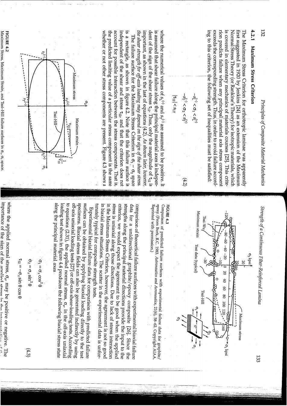
FIGURE 4.2 Maximum Stress,Maximum Strain,and Tsai-Hill failure surfaces in o,o2 space. laximum stress Maximum strain whether or not other stress components are present.Figure 4.3 shows a the predicted limiting value of a particular stress component is the same account for possible interaction between the stress components.That is, independent of the shear and stress t2,and that the criterion does not is a rectangle,as shown in figure 4.2.Note that this failure surface is The failure surface for the Maximum Stress Criterion in 01-02 space the shear strength for off-axis loading may depend on the sign of the shear stress. important,as shown in the last of equations(4.2).As shown later,however, dent of the sign of the shear stress t.Thus,only the magnitude of t2 is is assumed that shear failure along the principal material axes is indepen- where the numerical values of s)and s-)are assumed to be positive.It -s<01<) ing to this criterion,the following set of inequalities must be satisfied: exceeds the corresponding strength.Thus,in order to avoid failure accord- rion predicts failure when any principal material axis stress component is covered in elementary mechanics of materials courses [25].This crite- Normal Stress Theory(or Rankine's Theory)for isotropic materials,which first suggested in 1920 by Jenkins [24]as an extension of the Maximum The Maximum Stress Criterion for orthotropic laminae was apparently 4.2.1 Maximum Stress Criterion Principles of Composite Material Mechanics FIGURE 4.3 where the applied normal stress,ox,may be positive or negative.The importance of the sign of the annlied streee inthe along the principal material axes Maximum strain T12=-0x sin 0 cos 0 2=Ox sin20 to equations (2.31),the applied normal stress,o in the off-axis uniaxial loading test shown in figure 4.4 produces the following biaxial stress state off-axis uniaxial loading tests [27]or off-axis shear-loading tests.According surfaces can be obtained by applying biaxial loading directly to the test specimens.Biaxial stress fields can also be generated indirectly by using Experimental biaxial failure data for comparison with predicted failure in biaxial stress situations.The scatter in the experimental data is unfor- 财。tur stress is uniaxial along those directions.Due to lack of stress interaction in the Maximum Stress Criterion,however,the agreement is not so good strengths along the principal material directions provide the input to the criterion,we would expect the agreement to be good when the applied data for a unidirectional graphite/epoxy composite [26].Since the comparison of theoretical failure surfaces with experimental biaxial failure Reprinted with permission.) Comparison of predicted failure surfaces with experimental failure data for graphite epoxy.(From Burk,R.C.1983.Astronautics and Aeronautics,21(6),58-62.Copyright AIAA Test data(typical -80-60-40-20 - Tsai-Hill 20406080100120 Strength of a Continuous Fiber-Reinforced Lamina Maximum stress 芬

FIGURE 4.5 evaluated 28. FIGURE 4.4 Off-axis shear test of a unidirectional lamina specimen.(a)Positive(b)negative T12 =Txy (cos20-sin20) 02=-2Txy cos0 sin 0 01=2Txy cos0 sin 0 material axes according to equations (2.31): stress,t generates the following biaxial stress state along the principal For the off-axis shear test described in figure 4.5,the applied shear failure versus lamina orientation,0,the various failure criteria can be failure surfaces.By plotting the predicted and measured values of o,at stituted into equations similar to equations (4.2)in order to generate test results here is obvious.These stress components may then be sub- Off-axis uniaxial test of a unidirectional lamina specimen Principles of Composite Material Mechanics failure is 2=-2tx Cos0sin0=-2T.sin For failure by the transverse compressive stress: Txy =1448MPa So the corresponding off-axis shear stress required to produce this mode of 1=27yc0605n8-2700094528m450-7g-5m-1448MPa For failure by the longitudinal tensile stress, Criterion,along with the strength data for T300/5208 from table 4.1,the calculations are as follows: produces longitudinal tension and transverse compression along the prin- cipal material axes.Employing equations(2.31)and the Maximum Stress Solution.From figure 4.5(a),it is seen that a positive off-axis shear stress in figure 4.5(a).Determine the value of the off-axis shear stressthat would cause failure according to the Maximum Stress Criterion. is subjected to a positive off-axis shear stress,at an angle45 as shown An element of an orthotropic lamina made of T300/5208 carbon/epoxy material phases of stress analysis in composite materials. interpretation of tests results as described here;it has implications for all axes shows that the sign of the shear stress makes no difference in that case.The importance of the sign of the shear stress extends beyond the failure.A similar development for pure shear along the principal material shear stress of a certain magnitude could cause a transverse tensile failure, whereas a positive shear stress of the same magnitude would not cause should now be obvious.It is easy to visualize a situation where a negative (table 4.1),the importance of the sign of the applied off-axis shear stress and transverse tension,as shown in figure 4.5(b).Given the fact that the transverse tensile strength is so much lower than the other strengths a negative applied shear stress would produce longitudinal compression would produce longitudinal tension and transverse compression along the principal material axes,as shown in figure 4.5(a).On the other hand, is warranted.For example,if the angle 0=45,equations(4.4)reduce to 1=Ty02=-Yy and t2=0.Thus,a positive applied shear stress,t tation of test results may not be so obvious here,and further discussion The importance of the sign of the applied shear stress in the interpre- Strength of a Continuous Fiber-Reinforced Lamina

failure is: failure is: For failure by the transverse tensile stress, For failure by the longitudinal compressive stress, calculations are now as follows: t话话。5(0) EXAMPLE 4.2 failure is: 1P-44.3M2a So the corresponding off-axis shear stress required to produce this mode of 025270008941m0-27000945·54m45-79:50-4482Pa 10-1443M29 So the corresponding off-axis shear stress required to produce this mode of G1-279080800-27000845.8m45--70-850--1448.vea Criterion,along with the strength data for T300/5208 from table 4.1,the cipal material axes.Employing equation(2.31)and the Maximum Stress produces longitudinal compression and transverse tension along the prin- Solution.From figure 4.5(b),it is seen that a negative off-axis shear stress Repeat example 4.1 if the off-axis shear stress in example 4.1 is negative,as shown 101248M1a of the off-axis shear stress required to produce failure is: So transverse compression is the governing mode of failure,and the value Tn2 =Tx(cos20-sin20)=txy (cos245-sin2 45")=0 There is no shear stress along the principal material axes,since Txy =248MPa So the corresponding off-axis shear stress required to produce this mode of Principles of Composite Material Mechanics satisfied: strain relationships in equation (2 241rith. shear strain Y2. failure stress. now only skewed parallelogram,as shown in figure 4.2 and figure 4.3.The shape of the parallelogram can be deduced by combining the lamina stress- similar to that of the Maximum Stress Criterion in o1-02 space.In 01-02 space,however,the Maximum Strain Criterion failure surface is a surface for the Maximum Strain Criterion in e1-E2 space is a rectangle Due to the similarity of equation(4.5)and equation(4.2),the failure failure along the principal material axes is independent of the sign of the (4.1).As with the Maximum Stress Criterion,it is assumed that shear where the numerical values of e)and e)are assumed to be positive and the ultimate strains are all engineering strains as defined by equation -et)<e<e) according to this criterion,the following set of inequalities must be rion predicts failure when any principal material axis strain component exceeds the corresponding ultimate strain.In order to avoid failure discussed in elementary mechanics of materials courses [251.This crite- Theory (or Saint Venant's Theory)for isotropic materials,which is also In 1967,Waddoups [29]proposed the Maximum Strain Criterion for orthotropic laminae as an extension of the Maximum Normal Strain 4.2.2 Maximum Strain Criterion negative produces a completely different mode of failure and a much lower So simply changing the sign of the off-axis shear stress from positive to T-44329 So transverse tension is now the governing mode of failure,and the corre- sponding value of the off-axis shear stress required to produce failure is t5-t0o0820-51m200-78C0s:430-8m2450-0 Again there is no shear stress along the principal material axes,since Strength of a Continuous Fiber-Reinforced Lamina 三

simple. 1 direction is and maximum strain criteria in that they include terms to account for theories for isotropic materials,but they differ from the maximum stress The so-called quadratic interaction criteria also evolved from early failure 4.2.3 Quadratic Interaction Criteria for orthotropic materials because the resulting equations are relatively data have led to similar conclusions [28],but both criteria are still used biaxial failure data for graphite/epoxy in figure 4.3.Off-axis uniaxial test dicted failure surface does not show good agreement with experimental account for possible interaction between stress components,and the pre- Maximum Stress Criterion,the Maximum Strain Criterion does not same for the maximum stress and maximum strain criteria.As with the are satisfied.Only for isotropic materials are the intercepts always the to stress space unless certain mathematical constraints on the properties tions develop as a result of an ambiguous conversion from strain space tradicts experimental evidence [5,8].According to Wu [5],such contradic- the measured tensile and compressive longitudinal strengths,which con- Criterion parallelogram intercept the horizontal axis at stresses less than rials,the lines defining the top and bottom of the Maximum Strain of the Maximum Stress Criterion rectangle in stress space.For some mate- Maximum Strain Criterion parallelogram may not be the same as those nitudes of the lamina strengths and stiffnesses,the intercepts of the ing two sides.It should be noted,however,that depending on the mag- strains in the negative 1 and 2 directions yields equations for the remain- ogram shown in figure 4.2,and similar consideration of the limiting va These lines form the right and top sides,respectively,of the parallel- which is the equation for a straight line having intercept(0,s))and slope 21801483 positive 2 direction yields the equation: 1/v12(fig.4.2).A similar development using the limiting strain along the which is the equation of a straight line having intercept(sL(),0)and slope 9/ V12 9 equation(4.1).For example,the limiting strain associated with the positive Principles of Composite Material Mechanics 多 S assumed to be the same.Solving equation(4.10)and equation(4.11)simul- taneously for A,B,and C,we find that tions,respectively.The yield strengths in tension and compression are where Y2 and Y3 are the uniaxial yield strengths along the 2 and 3 direc- along the 2 and 3 directions give the equations where Yi is the yield strength along 1 direction.Similarly,uniaxial tests to zero equation(4.9)reduces to: uniaxial test along the 1 direction with o1=Yi and all other stresses equal (4.9)must be <1,and failure is predicted if the left-hand side is 21.For a or shear loading.In order to avoid failure,the left-hand side of equation where A,B,C,D,E,and F are determined from yield strengths in uniaxial A(62-G3)2+B(03-G1)2+C(01-02)2+2Dt+2Et3+2Fti=1 (4.9) the Hill Criterion in o02,and o3 space is described by the equation: three-dimensional state of stress along the principal axes of anisotropy (the 123 axes)in such a material,the failure surface (or yield surface)for could be modified to include the effects of induced anisotropic behavior in initially isotropic metals during large plastic deformations.For a general quadratic interaction criteria for predicting the onset of yielding in iso- tropic metals [25].In 1948,Hill [30]suggested that the von Mises Criterion in any mechanics of materials book,the maximum distortional energy criterion or von Mises Criterion(circa early 1900s)is the most widely used the equations for plane stress lead to elliptical failure surfaces.As shown interaction between the stress components,and the quadratic forms of Strength of a Continuous Fiber-Reinforced Lamina 412 (410

stress space. 40080n6s: the prediction of yielding in ductile metals,the equations are based on Since the von Mises and Hill Criteria are phenomenological theories for interaction criteria based on the von Mises model,there is another problem. In addition to the previously mentioned limitations of the quadratic 2,and oa,as suggested by Hoffman [33] compression is to include terms that are linear in the normal stresses ou One way to account for different strengths in tension and well for the graphite/epoxy material except for the fourth quadrant of [25,32].As shown in figure 4.3,the procedure seems to work reasonably Mises and Hill Criteria,it has been successfully used for some composites is inconsistent with the assumptions used in formulating the original von for the case of graphite/epoxy in figure 4.3.Although such a procedure resulting failure surface is no longer symmetric about the origin,as shown negative,the values of sL()and s)would be used in equation (4.14).The for each quadrant of stress space.For example,if o is positive and o2 is strengths are different by simply using the appropriate value of st and sr The Tsai-Hill equation can be used when tensile and compressive because of the assumption of equal strengths in tension and compression. figure 4.2.The ellipse shown in figure 4.2 is symmetric about the origin The.failure surface generated by this equation is an ellipse,as shown in equation(4.14)is <1,and failure is predicted if the left-hand side is 2L As with the Hill equation,failure is avoided if the left-hand side of for the Tsai-Hill failure surface: 9 三、+元⊙ equation(4.9),equation(4.12),and equation(4.13)reduce to the equation effective lamina strengths,then Y1=sL Y2=Y3 =sp and Y12=sLp and and if Hill's anisotropic yield strengths are replaced by the corresponding the reinforcement direction,if plane stress is assumed (03=31=723=0), axes of the transversely isotropic lamina,with the 1 direction being along Criterion.If the 123 directions are assumed to be the principal material and Tsai [32];the resulting equation is often referred to as the Tsai-Hill tropic,transversely isotropic lamina was suggested by Azzi and Tsai [31] The extension of the Hill Criterion to prediction of failure in an ortho- 12,23,and 31 planes,respectively. where Yi2,Y2s,and Ys are the yield strengths in shear associated with the Similarly,for pure shear tests along the 23,31,and 12 planes,equation Principles of Composite Material Mechanics (4·13 am neous solution of the two equations resulting from equation(4.16)yields: of the uniaxial and shear strengths using the same approach that was used with the Hill Criterion.For example,for the tension and compression tests with uniaxial stresses 01=s()and o1=sL,respectively,simulta- of F,all the strength tensors in equation(4.16)can be expressed in terms strengths in tension and compression.In addition,the term 2F120102 takes into account interaction between the normal stresses.With the exception stress 0.remains.However,the linear terms in the normal stresses o1=ou and 02=022 are retained because they take into account the different because the shear strength along the principal material axes is not affected by the sign of the shear stress.Thus,only a quadratic term in the shear where the linear terms in the shear stress 0o=t12 have been dropped Fi+F202+F660+F01+F202+2F20102=1 For the case of plane stress with 03=0a3=0,0=T23=0,and os=T1=0, equation (4.15)becomes (4.15)must be <1,and failure is predicted when the left-hand side is 21. experimentally determined strength tensors of the second and fourth rank,respectively.In order to avoid failure,the left-hand side of equation where the contracted notation i,j=1,2,...,6 is used,and Fi and Fi are described by the tensor polynomial: Foi+Fojoj=1 been suggested earlier by Gol'denblat and Kopnov [35].In the Tsai-Wu general quadratic interaction criteria,the failure surface in stress space is of a tensor polynomial failure theory for anisotropic materials that had quadratic interaction criterion,which will be discussed next. In 1971,Tsai and Wu [34]proposed an improved and simplified version However,all of these theories turn out to be special cases of a more general of its linear terms,could predict failure for the hydrostatic state of stress. can produce shear strains and failure.Hoffman's equation [33],by virtue hydrostatic state of stress o1=02=03,and 2=23=T1=0.Due to shear coupling,however,a hydrostatic state of stress in an anisotropic material ing,and the Hill Criterion predicts that failure will never occur under a cause the slip and dislocation movements that are associated with yield- Experimental evidence suggests that a hydrostatic state of stress does not principal stress differences and the corresponding shear stresses and strains that drive slip and dislocation movement in metallic crystals. Strength of a Continuous Fiber-Reinforced Lamina (413 416 (415
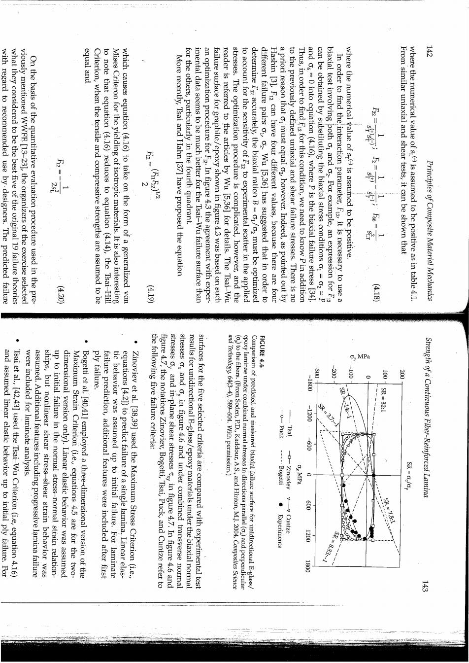
equal and with regard to recommended use by.designers.The predicted failure what they considered to be the best five of the original 19 failure theories viously mentioned WWFE [13-23],the organizers of the exercise selected On the basis of the quantitative evaluation procedure used in the pre- Criterion,when the tensile and compressive strengths are assumed to be to note that equation (4.16)reduces to equation (4.14),the Tsai-Hill Mises Criteron for the yielding of isotropic materials.It is also interesting which causes equation (4.16)to take on the form of a generalized von More recently,Tsai and Hahn [37]have proposed the equation for the others,particularly in the fourth quadrant. imental data seems to be much better for the Tsai-Wu failure surface than an optimization procedure for FR In figure 4.3 the agreement with exper- failure surface for graphite/epoxy shown in figure 4.3 was based on such reader is referred to the articles by Wu [5,36]for details.The Tsai-Wu stresses.The optimization procedure is complicated,however,and the to account for the sensitivity of F1z to experimental scatter in the applied determine F2 accurately,the biaxial ration B=01/02 must be optimized different failure pairs o1,02.Wu [5,361 has suggested that in order to Hashin [31,F12 can have four different values,because there are four a priori reason that o1 must equal oz,however.Indeed,as pointed out by to the previously defined uniaxial and shear failure stresses.There is no Thus,in order to find F for this condition,we need to know P in addition and o=0 into equation(4.16),where p is the biaxial failure stress [34] can be obtained by substituting the biaxial stress conditions o1=02=p biaxial test involving both o1 and c2.For example,an expression for F In order to find theinteraction parameter,Fi2,it is necessary to use a where the numerical value of s)is assumed to be positive. From similar uniaxial and shear tests,it can be shown that where the numerical value of s)is assumed to be positive as in table 4.1. Principles of Composite Material Mechanics (420 (6.19 (418 · ply failure. stresses oy FIGURE 4.6 o,MPa -200 -100 兰 1800 and assumed linear elastic behavior up to initial ply failure.For Tsai et al.,[42,43]used the Tsai-Wu Criterion(i.e,equation 4.16) assumed.Additional features including progressive lamina failure were included for laminate analysis. ships,but nonlinear shear stress-shear strain behavior was up to initial failure in the normal stress-normal strain relation- dimensional version only).Linear elastic behavior was assumed Maximum Strain Criterion (i.e.,equations 4.5 are for the two- Bogetti et al.[40,41]employed a three-dimensional version of the failure prediction,additional features were included after first tic behavior was assumed up to initial failure.For laminate equations [4.21)to predict failure of a single lamina.Linear elas- Zinoviev et al.[38,39]used the Maximum Stress Criterion (i.e., the following five failure criteria: figure 4.7,the notations Zinoviev,Bogetti,Tsai,Puck,and Cuntze refer to and in-plane shear stresses txy in figure 4.7.In figure 4.6 and stresses ox and oy in figure 4.6 and under combined transverse normal results for unidirectional E-glass/epoxy materials under the biaxial normal surfaces for the five selected criteria are compared with experimental test and Technology,64(3-4),589-604.With permission.) epoxy laminae under combined normal stresses in directions parallel()and perpendicular ()to the fibers.(From Soden,P.D.,Kaddour,A.S.,and Hinton,M.J.2004.Composites Science Comparison of predicted and measured biaxial failure surface for unidirectional E-glass SR=32:1 -0 -200 3.7 -600 ---Bogetti Strength of a Continuous Fiber-Reinforced Lamina Ox MPa Experiments Cuntze g88

was added. FIGURE 4.7 should be selected for the purpose of lamina design. Txy MPa that produces the innermost portion of the failure surface in that quadrant such a way that,for a given quadrant of the failure surface,the theory mended that the combined theories of Tsai,Puck,and Cuntze be used in in several regions of both figure 4.6 and figure 4.7.Finally,it was recom- predictions of Zinoviev and Bogetti were observed to be unconservative sion-compression of figure 4.6,but fared better overall in figure 4.7.The data.The Puck predictions appeared to be unconservative in the ten- compression quadrant of figure 4.6 where there is a lack of experimental were believed to be potentially unconservative in the compression- ment with available experimental data [19].However,the Tsai predictions that the predictions of Tsai,Puck,and Cuntze gave the best overall agree- From figure 4.6 and figure 4.7,the organizers of the WWFE observed beyond the scope of this book. similar three-dimensional progressive failure theories,which are Puck and Schurmann [44,45]and Cuntze et al.[46,47]employed laminate failure prediction,a progressive failure analysis feature Technology,64(34),589-604.With permission.) fibers ()(From Soden,P.D.,Kaddour,A.S.,and Hinton,M.J.2004.Composites Sciencend laminae under combined in-plane shear stress (and normal stress perpendicular to the Comparison of predicted and measured failure surfaces for unidirectional E-glass/epoxy 罗 营 S L:8S'I- Tsai 100 Cuntze ,MTkx 电e Bogetti SR 1:2.】 Principles of Composite Material Mechanics P:1.62MPa. found as follows: theories EXAMPLE 4.3 be presented. (110312 (b)For the Tsai-Hill Criterion,equation(4.14)yields Thus,the transverse tensile failure governs,and failure occurs first at 0=6.0p=Sur=82.7 MPa;therefore,p=13.78 MPa 2=17.0p =s=27.6 MPa;therefore,p=1.62 MPa 1=20.5p=sL()=1103 MPa;therefore,p=53.8 MPa (a)For the Maximum Stress Criterion,the three possible values of p at failure are 2.3,1=20.5p,2=17.0p,and 12=6.0p (all in MPa).Note that both normal stresses are positive,so that the tensile strengths should be used in the failure Solution.The first step in the application of both theories is to determine the stresses along the principal material axes.From the results of example internal pressure p,which would cause failure of the vessel according to (a)the Maximum Stress Criterion and (b)the Tsai-Hill Criterion. The filament wound pressure vessel described in example 2.3 is fabricated from E-glass/epoxy having the lamina strengths listed in table 4.1.Determine the several micromechanical models for predicting composite strength will micromechanical behavior of fiber and matrix materials.In the next section, on the macromechanical behavior of the composite without regard for the systematic experimental verification of the various theories for a variety of stress conditions.Finally,the theories discussed in this section are based Although considerable progress has been made,there is still a need for the particular case of failure in laminated tubes under internal pressure loading,the cubic criterion is more accurate than the quadratic criterion. include cubic terms.Obviously,the evaluation of the strength parameters in such an equation is a formidable task.It was shown,however,that in failure modes should be modeled separately by a quadratic criterion. Tennyson et al.[48]have extended the tensor polynomial criterion to and its contributing stresses should be identified,and that each of these ites continues to be the subject of numerous publications.For example, Hashin [3,4]has suggested that for a given composite,each failure mode The development of improved multiaxial strength criteria for compos- Strength of a Continuous Fiber-Reinforced Lamina 器