
@月命大凳 Chapter 3 Generic channel models Graduate course:Propagation Channel Characterization,Parameter Estimation and Modeling 52/199
Graduate course: Propagation Channel Characterization, Parameter Estimation and Modeling 52 / 199 Chapter 3 Generic channel models
@月冷大学 3.1 Physical propagation mechanisms Reflection,diffraction and scattering are three basic propagation mechanism. They occur depending on the size L of the object compared with the wavelength入. When a plane electromagnetic wave encounters an obstacle much larger than the wavelength,i.e.L,reflection occurs. Diffraction happens when the obstacle's size is in the same order of the wavelength,i.e.L≈λ. Scattering happens when a plane wave encounters an obstacle much smaller than the wavelength,i.e.L<<.This obstacle becomes a new source emitting waves towards multiple directions. Graduate course:Propagation Channel Characterization,Parameter Estimation and Modeling 53/199
3.1 Physical propagation mechanisms Graduate course: Propagation Channel Characterization, Parameter Estimation and Modeling 53 / 199 ■ Reflection, diffraction and scattering are three basic propagation mechanism. ■ They occur depending on the size L of the object compared with the wavelength λ. ◆ When a plane electromagnetic wave encounters an obstacle much larger than the wavelength, i.e. L ≫ λ, reflection occurs. ◆ Diffraction happens when the obstacle’s size is in the same order of the wavelength, i.e. L ≈ λ. ◆ Scattering happens when a plane wave encounters an obstacle much smaller than the wavelength, i.e. L << λ. This obstacle becomes a new source emitting waves towards multiple directions
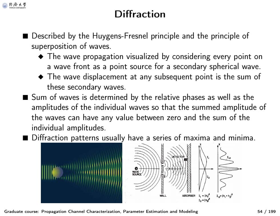
@月合大等 Diffraction Described by the Huygens-Fresnel principle and the principle of superposition of waves. The wave propagation visualized by considering every point on a wave front as a point source for a secondary spherical wave. The wave displacement at any subsequent point is the sum of these secondary waves. Sum of waves is determined by the relative phases as well as the amplitudes of the individual waves so that the summed amplitude of the waves can have any value between zero and the sum of the individual amplitudes. ■ Diffraction patterns usually have a series of maxima and minima. 122h,+h Graduate course:Propagation Channel Characterization,Parameter Estimation and Modeling 54/199
Diffraction Graduate course: Propagation Channel Characterization, Parameter Estimation and Modeling 54 / 199 ■ Described by the Huygens-Fresnel principle and the principle of superposition of waves. ◆ The wave propagation visualized by considering every point on a wave front as a point source for a secondary spherical wave. ◆ The wave displacement at any subsequent point is the sum of these secondary waves. ■ Sum of waves is determined by the relative phases as well as the amplitudes of the individual waves so that the summed amplitude of the waves can have any value between zero and the sum of the individual amplitudes. ■ Diffraction patterns usually have a series of maxima and minima

@月冷大学 Experimental propagation constellation Parameter estimation algorithms estimated direction of arrival, direction of departure,delay,Doppler frequency and complex attenuation of plane waves ■ With knowledge of the locations of the Tx and Rx,propagation paths especially for those with one-bounce can be constructed. Estimated paths overlapping with the photographs of the background. Estimated Directions of Arrival(DoAs) Reconstructed Paths D T11 B2 Estimated Directions of Departure(DoDs) Graduate course:Propagation Channel Characterization,Parameter Estimation and Modeling 55/199
Experimental propagation constellation Graduate course: Propagation Channel Characterization, Parameter Estimation and Modeling 55 / 199 ■ Parameter estimation algorithms estimated direction of arrival, direction of departure, delay, Doppler frequency and complex attenuation of plane waves ■ With knowledge of the locations of the Tx and Rx, propagation paths especially for those with one-bounce can be constructed. Estimated paths overlapping with the photographs of the bac E kground. Estimated Directions of Arrival (DoAs) Reconstructed Paths Estimated Directions of Departure (DoDs) 25 24 23 22 21 20 19 17 18 1615 14 13 12 11 10 9 8 5 7 6 4 3 2 1 Azimuth [°] Coelevation [°] 40 30 20 10 0 -10 -20 -30 -40 -50 85 90 95 100 105 110 25 24 23 22 21 20 19 18 17 16 15 14 13 12 11 10 98 674532 1 Azimuth [°] Coelevation [°] 150 100 50 0 -50 -100 -150 60 80 100 120 Relative delay [ns] 0 82 164 246 329 23 22 21 12 25 24 7 Tx 2 1 15 6 5 10 3 4 13 11 16 17 Rx 9 18 14 8 19 20

@月合大等 Identified propagation mechanism ■ No.1,to 6 paths are due to the diffraction at the edge of building “B3 Estimated Directions of Arrival (DoAs) Reconstructed Paths D (10 ①u0⊙0 11 10 110 10 Azimuth[] B3 Estimated Directions of Departure (DoDs U10 222 100 120 10 0 -50 -100 -150 Azimuth [ 10m 82 164 246 Relative delay [ns] Graduate course:Propagation Channel Characterization,Parameter Estimation and Modeling 56/199
Identified propagation mechanism Graduate course: Propagation Channel Characterization, Parameter Estimation and Modeling 56 / 199 ■ No. 1, to 6 paths are due to the diffraction at the edge of building “B3”. Estimated Directions of Arrival (DoAs) Reconstructed Paths Estimated Directions of Departure (DoDs) 25 24 23 22 21 20 19 17 18 1615 14 13 12 11 10 9 8 5 7 6 4 3 2 1 Azimuth [°] Coelevation [°] 40 30 20 10 0 -10 -20 -30 -40 -50 85 90 95 100 105 110 25 24 23 22 21 20 19 18 17 16 15 14 13 12 11 10 98 674532 1 Azimuth [°] Coelevation [°] 150 100 50 0 -50 -100 -150 60 80 100 120 Relative delay [ns] 0 82 164 246 329 23 22 21 12 25 24 7 Tx 2 1 15 6 5 10 3 4 13 11 16 17 Rx 9 18 14 8 19 20
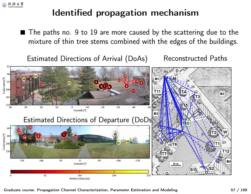
@月冷大等 ldentified propagation mechanism The paths no.9 to 19 are more caused by the scattering due to the mixture of thin tree stems combined with the edges of the buildings. Estimated Directions of Arrival (DoAs) Reconstructed Paths 81 T11 105 -10 Azimuth Estimated Directions of Departure (DoDs 10 U10 18)2 0 -100 -10 Azimuth 10m. 16 24 Relative delay[ns】 Graduate course:Propagation Channel Characterization,Parameter Estimation and Modeling 57/199
Identified propagation mechanism Graduate course: Propagation Channel Characterization, Parameter Estimation and Modeling 57 / 199 ■ The paths no. 9 to 19 are more caused by the scattering due to th e mixture of thin tree stems combined with the edges of the buildings. Estimated Directions of Arrival (DoAs) Reconstructed Paths Estimated Directions of Departure (DoDs) 25 24 23 22 21 20 19 17 18 1615 14 13 12 11 10 9 8 5 7 6 4 3 2 1 Azimuth [°] Coelevation [°] 40 30 20 10 0 -10 -20 -30 -40 -50 85 90 95 100 105 110 25 24 23 22 21 20 19 18 17 16 15 14 13 12 11 10 98 674532 1 Azimuth [°] Coelevation [°] 150 100 50 0 -50 -100 -150 60 80 100 120 Relative delay [ns] 0 82 164 246 329 23 22 21 12 25 24 7 Tx 2 1 15 6 5 10 3 4 13 11 16 17 Rx 9 18 14 8 19 20
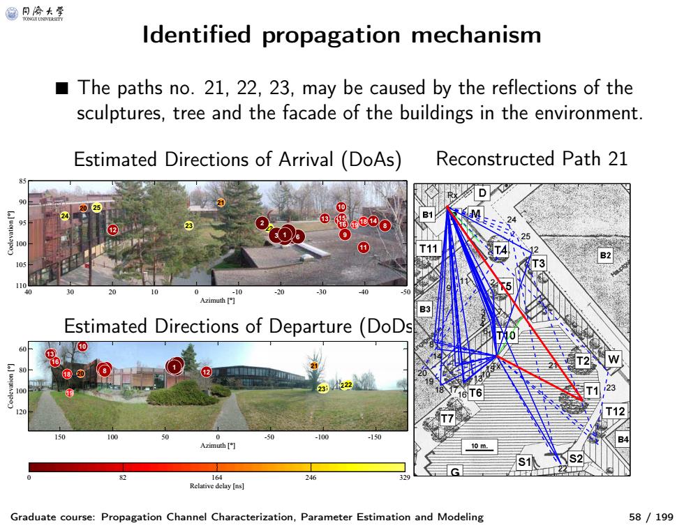
@月合大等 Identified propagation mechanism The paths no.21,22,23,may be caused by the reflections of the sculptures,tree and the facade of the buildings in the environment Estimated Directions of Arrival (DoAs) Reconstructed Path 21 ①tEoo 100 0 11 105 110 10 Azimuth[ Estimated Directions of Departure (DoDs U10 222 100 120 10 0 0 -50 -100 -150 Azimuth [ 10m 82 164 246 Relative delay [ns] Graduate course:Propagation Channel Characterization,Parameter Estimation and Modeling 58/199
Identified propagation mechanism Graduate course: Propagation Channel Characterization, Parameter Estimation and Modeling 58 / 199 ■ The paths no. 21, 22, 23, may be caused by the reflections of the sculptures, tree and the facade of the buildings in the environment. Estimated Directions of Arrival (DoAs) Reconstructed Path 21 Estimated Directions of Departure (DoDs) 25 24 23 22 21 20 19 17 18 1615 14 13 12 11 10 9 8 5 7 6 4 3 2 1 Azimuth [°] Coelevation [°] 40 30 20 10 0 -10 -20 -30 -40 -50 85 90 95 100 105 110 25 24 23 22 21 20 19 18 17 16 15 14 13 12 11 10 98 674532 1 Azimuth [°] Coelevation [°] 150 100 50 0 -50 -100 -150 60 80 100 120 Relative delay [ns] 0 82 164 246 329 23 22 21 12 25 24 7 Tx 2 1 15 6 5 10 3 4 13 11 16 17 Rx 9 18 14 8 19 20
@月冷大等 ldentified propagation mechanism The paths no.24,may be caused by the reflections of the sculptures and the facade of the buildings in the environment. Estimated Directions of Arrival (DoAs) Reconstructed Path 24 D T11 105 -10 Azimuth Estimated Directions of Departure (DoDs 10 18 0 -100 -150 Azimuth 10m. 164 24 Relative delay[ns】 Graduate course:Propagation Channel Characterization,Parameter Estimation and Modeling 59/199
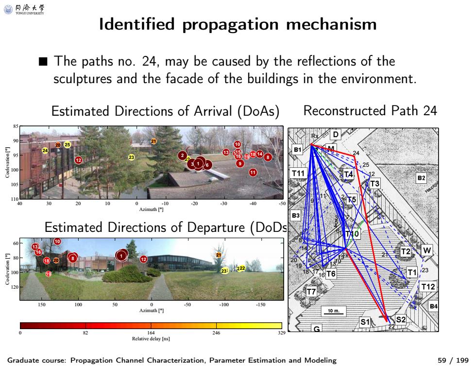
Identified propagation mechanism Graduate course: Propagation Channel Characterization, Parameter Estimation and Modeling 59 / 199 ■ The paths no. 24, may be caused by the reflections of the sculptures and the facade of the buildings in the environment. Estimated Directions of Arrival (DoAs) Reconstructed Path 24 Estimated Directions of Departure (DoDs) 25 24 23 22 21 20 19 17 18 1615 14 13 12 11 10 9 8 5 7 6 4 3 2 1 Azimuth [°] Coelevation [°] 40 30 20 10 0 -10 -20 -30 -40 -50 85 90 95 100 105 110 25 24 23 22 21 20 19 18 17 16 15 14 13 12 11 10 98 674532 1 Azimuth [°] Coelevation [°] 150 100 50 0 -50 -100 -150 60 80 100 120 Relative delay [ns] 0 82 164 246 329 23 22 21 12 25 24 7 Tx 2 1 15 6 5 10 3 4 13 11 16 17 Rx 9 18 14 8 19 20

@月命卡 Mechanism identified by polarization properties Estimated polarization: 164 A Relative delay [ns 卉产·光 Blue ellipses:polarization ellipses calculated using d,1,1 d2,1, Red ellipses:polarization ellipses calculated using d1,2 0d.221T Graduate course:Propagation Channel Characterization,Parameter Estimation and Modeling 60/199
Mechanism identified by polarization properties Graduate course: Propagation Channel Characterization, Parameter Estimation and Modeling 60 / 199 Estimated polarization: 25 24 23 22 21 20 19 17 18 1615 14 13 12 11 10 9 8 5 7 6 4 3 2 1 Azimuth [°] Coelevation [°] 40 30 20 10 0 -10 -20 -30 -40 -50 85 90 95 100 105 110 Relative delay [ns] 0 82 164 246 329 40 30 20 10 0 −10 −20 −30 −40 −50 85 90 95 100 105 110 1 2 3 4 5 7 6 8 9 10 11 12 13 14 15 16 17 18 19 20 21 22 23 24 25 Azimuth [°] Coelevation [°] ■ Blue ellipses : polarization ellipses calculated using aˆd, 1,1 aˆd, 2,1 T , ■ Red ellipses : polarization ellipses calculated using aˆd, 1,2 aˆd, 2,2 T .����
@月冷大学 Mechanism identified by polarization properties Scatter plot of the estimated cross-polarization discrimination (XPD)of the individual paths: 30 7,E G刃 25 55E3F 4,E 20 6,Ex 1,E (G2a) 25,TF 16, 网 fe.I in dB 10 11,FR 14,F× 13,T 8,F9,FR ×15,T 17T 23,TW 19TFB× 20,FF 21,T -5 ×10,T 22,S *24,SF 5 0 5 10 15 20 25 30 f.in dB 2 12 ■fe,1=ae,1,1/ae2,1 and fe,2=d0,2,2/ae,1,21 The symbols denote the types of scatterers identified along the paths:facade(F),roof (R),edge(E)of buildings as well as tree (T),sculpture (S),and wall (W) Graduate course:Propagation Channel Characterization,Parameter Estimation and Modeling 61/199
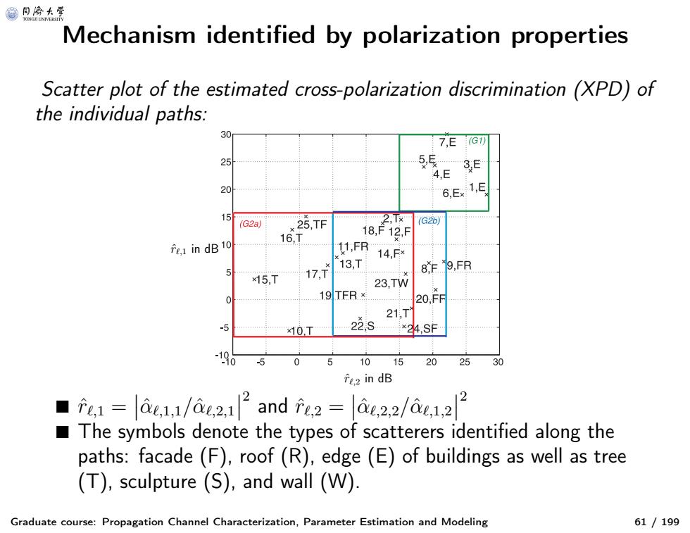
Mechanism identified by polarization properties Graduate course: Propagation Channel Characterization, Parameter Estimation and Modeling 61 / 199 Scatter plot of the estimated cross-polarization discrimination (XPD) of the individual paths: rˆℓ,1 in dB rˆℓ,2 in dB ■ rˆℓ, 1 = αˆℓ, 1,1 / αˆℓ, 2,1 2 and rˆℓ, 2 = αˆℓ, 2,2 / αˆℓ, 1,2 2 ■ The symbols denote the types of scatterers identified along the paths: facade (F), roof (R), edge (E) of buildings as well as tree (T), sculpture (S), and wall (W)