Deterministic radio propagation modeling and ray tracing 1) Introduction to deterministic propagation modelling 2) Geometrical Theory of Propagation I-The ray concept-Reflection and transmission 3) Geometrical Theory of Propagation II-Diffraction.multipath 4) Ray Tracing I 5) Ray Tracing II-Diffuse scattering modelling 6) Deterministic channel modelling I 7) Deterministic channel modelling II-Examples 8) Project -discussion
Deterministic radio propagation modeling and ray tracing 1) Introduction to deterministic propagation modelling 2) Geometrical Theory of Propagation I - The ray concept – Reflection and transmission 3) Geometrical Theory of Propagation II - Diffraction, multipath 4) Ray Tracing I 5) Ray Tracing II – Diffuse scattering modelling 6) Deterministic channel modelling I 7) Deterministic channel modelling II – Examples 8) Project - discussion
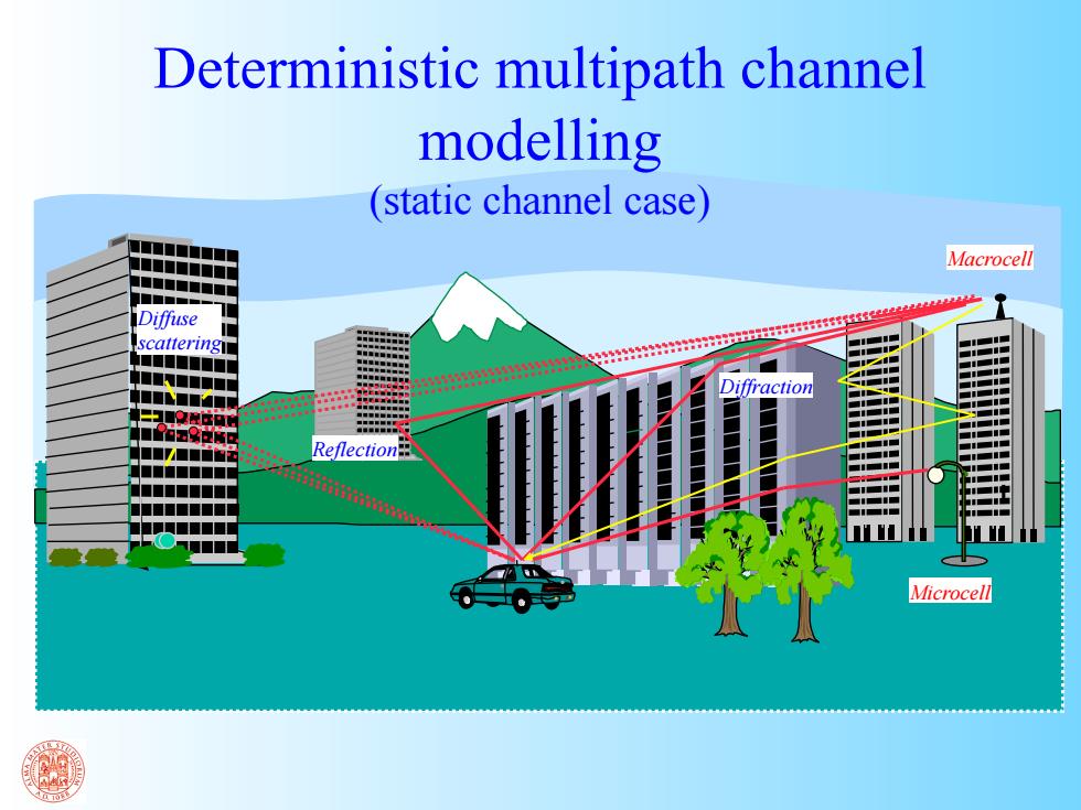
Deterministic multipath channel modelling (static channel case) Macrocell ■■■■■■ Diffuse scattering ■■■■ Diffraction ■■■ ■■■■ Reflection ■■■■■■ ■■ ■■ Microcell
Diffraction Microcell Macrocell Diffuse scattering Reflection Deterministic multipath channel modelling (static channel case)
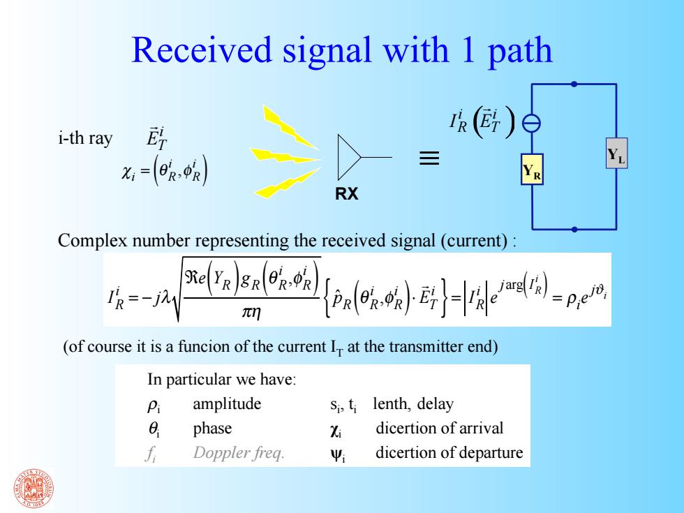
Received signal with 1 path i-th ray 欧 ()白 x:=(0R.0R) 三 囟 RX Complex number representing the received signal(current) BelYR)gnl0z-0k R=-j π功 )-e时=pe (of course it is a funcion of the current I at the transmitter end) In particular we have: P amplitude Si,ti lenth,delay 8 phase % dicertion of arrival Doppler freq. 4 dicertion of departure
Received signal with 1 path IR i = − jλ ℜe Y( R ) gR θ R i ,φ R i ( ) πη pˆR θ R i ,φ R i ( )⋅ ET i { } = IR i e jarg IR i ( ) = ρi e jϑi RX i-th ray χi = θ R i ,φ R i ( ) ≡ In particular we have: ρi amplitude θi phase fi Doppler freq. si , ti lenth, delay χi dicertion of arrival ψi dicertion of departure Complex number representing the received signal (current) : (of course it is a funcion of the current IT at the transmitter end) i ET ( ) i i R T I E YR YL
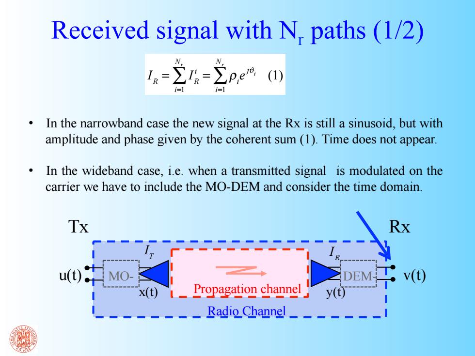
Received signal with N.paths (1/2) -2-2pe四 In the narrowband case the new signal at the Rx is still a sinusoid,but with amplitude and phase given by the coherent sum(1).Time does not appear. In the wideband case,i.e.when a transmitted signal is modulated on the carrier we have to include the MO-DEM and consider the time domain Tx Rx u0中Mo x(t)Propagation channel Radio Channel_
IR = IR i i=1 Nr ∑ = ρi e jϑi i=1 Nr ∑ (1) • In the narrowband case the new signal at the Rx is still a sinusoid, but with amplitude and phase given by the coherent sum (1). Time does not appear. • In the wideband case, i.e. when a transmitted signal is modulated on the carrier we have to include the MO-DEM and consider the time domain. Received signal with Nr paths (1/2) Tx Rx Radio Channel Propagation channel u(t) MO- DEM- v(t) x(t) y(t) IT IR
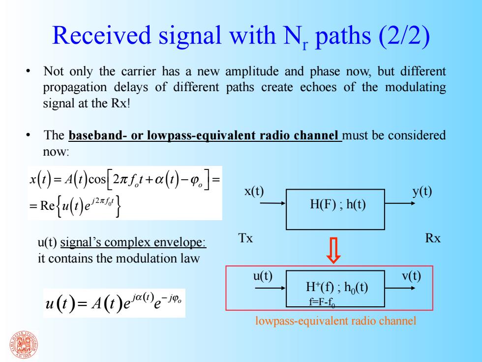
Received signal with N,paths(2/2) Not only the carrier has a new amplitude and phase now,but different propagation delays of different paths create echoes of the modulating signal at the Rx! The baseband-or lowpass-equivalent radio channel must be considered now: x(1)=A(t)cos[2zf.t+a()-0.J- x(t) -Refu(t)ex y(t) H(F);h(t) u(t)signal's complex envelope: Tx Rx it contains the modulation law u() v() H(0;h() u(t)=A(t)ee- f-F-fo lowpass-equivalent radio channel
x(t) y(t) H(F) ; h(t) u(t) v(t) H+(f) ; h0(t) f=F-f0 u(t) signal’s complex envelope: it contains the modulation law x(t) = A(t)cos 2π fo t +α (t) −ϕo ⎡ ⎣ ⎤ ⎦ = = Re u(t)e j2π f 0t { } ( ) ( ) ( ) o j t j u t A t e e α − ϕ = Received signal with Nr paths (2/2) • Not only the carrier has a new amplitude and phase now, but different propagation delays of different paths create echoes of the modulating signal at the Rx! • The baseband- or lowpass-equivalent radio channel must be considered now: Tx Rx lowpass-equivalent radio channel
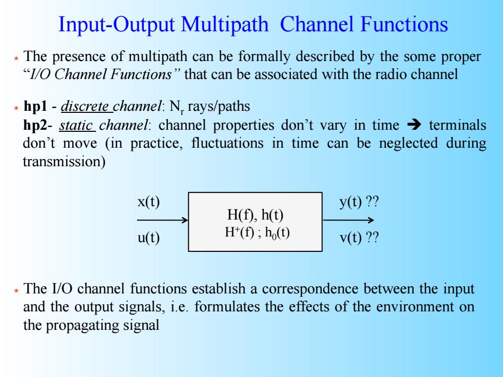
Input-Output Multipath Channel Functions The presence of multipath can be formally described by the some proper "1/O Channel Functions"that can be associated with the radio channel hpl-discrete channel:N,rays/paths hp2-static channel:channel properties don't vary in time>terminals don't move (in practice,fluctuations in time can be neglected during transmission) x() y(t)? H(f),h(t) u(t) H();h() v(t)? The I/O channel functions establish a correspondence between the input and the output signals,i.e.formulates the effects of the environment on the propagating signal
Input-Output Multipath Channel Functions The presence of multipath can be formally described by the some proper “I/O Channel Functions” that can be associated with the radio channel hp1 - discrete channel: Nr rays/paths hp2- static channel: channel properties don’t vary in time terminals don’t move (in practice, fluctuations in time can be neglected during transmission) H(f), h(t) H+(f) ; h0(t) y(t) ?? The I/O channel functions establish a correspondence between the input and the output signals, i.e. formulates the effects of the environment on the propagating signal v(t) ?? x(t) u(t)
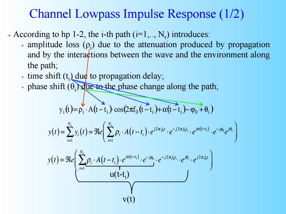
Channel Lowpass Impulse Response(1/2) According to hp 1-2,the i-th path(i=1,..,N.)introduces: amplitude loss (p)due to the attenuation produced by propagation and by the interactions between the wave and the environment along the path; time shift(t)due to propagation delay; phase shift(0)due to the phase change along the path; y)=pAt-t)cos2m,6≥t+6t)p+e,) y()()=icp 0=2A-小b-i).2 u(-t) V()
Channel Lowpass Impulse Response (1/2) According to hp 1-2, the i-th path (i=1,.., Nr ) introduces: amplitude loss (ρi ) due to the attenuation produced by propagation and by the interactions between the wave and the environment along the path; time shift (ti ) due to propagation delay; phase shift (θi ) due to the phase change along the path; y(t) = yi(t) = ℜ i=1 Nr ∑ e ρi ⋅ A t − t ( i)⋅ ej 2π f0t ⋅ e− j 2π f0ti ⋅ ejα t−t ( i) ⋅ e− jφ0 ejθi i=1 Nr ∑ ⎛ ⎝ ⎜ ⎞ ⎠ ⎟ ( ) ( ) ( ( ) ( ) ) i i i 0 i i 0 i y t = ρ ⋅A t − t ⋅cos 2πf t − t + α t − t − ϕ + θ y(t) = ℜe ρi ⋅ A t − t ( i)⋅ ejα t−t ( i) ⋅ e− jφ0 ⋅ e− j 2π f0ti ⋅ ejθi ⋅ ej 2π f0t i=1 Nr ∑ ⎛ ⎝ ⎜ ⎞ ⎠ ⎟ u(t-ti ) v(t)
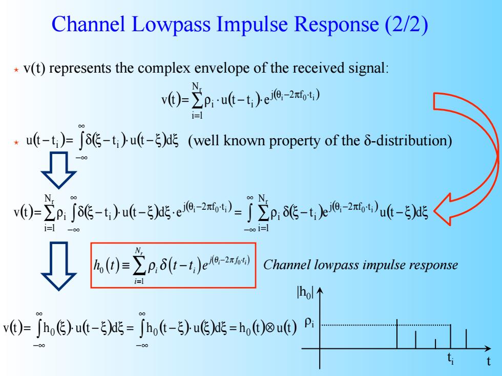
Channel Lowpass Impulse Response(2/2) v(t)represents the complex envelope of the received signal: v()-p.-u6-t)ct) i=l .u(t-t)=tutd(well known property of the 8-distribution) ↓ 60-2了能-f-gea--j2,c-ta0u6- k0=2p6t-4)4w网 Channel lowpass impulse response h个 v()-.G)w6-5)-Jb(-)uG)-h.()out)
Channel Lowpass Impulse Response (2/2) ( ) ( ) ( ) ∑ = θ − π ⋅ = ρ ⋅ − ⋅ r i 0 i N i 1 j 2 f t i i v t u t t e (well known property of the ( ) ( ) ( ) δ-distribution) ∫ ∞ −∞ u t − t = δ ξ − t ⋅u t − ξ dξ i i ( ) ( ) ( ) ( ) ( ) ( ) ( ) ∑ ∫ ∫ ∑ ∞ −∞ = θ − π ⋅ = θ − π ⋅ ∞ −∞ v t = ρ δ ξ − t ⋅u t − ξ dξ⋅e = ρ δ ξ − t e u t − ξ dξ r i 0 i r i 0 i N i 1 j 2 f t i i N i 1 j 2 f t i i v(t) represents the complex envelope of the received signal: h0 (t) ≡ ρi δ t − t ( i)ej θi−2π f0⋅t ( i) i=1 Nr ∑ v(t) h ( ) u(t )d h (t ) u( )d h (t) u(t) = ∫ 0 ξ ⋅ − ξ ξ = ∫ 0 − ξ ⋅ ξ ξ = 0 ⊗ ∞ −∞ ∞ −∞ |h0| t ti ρi Channel lowpass impulse response
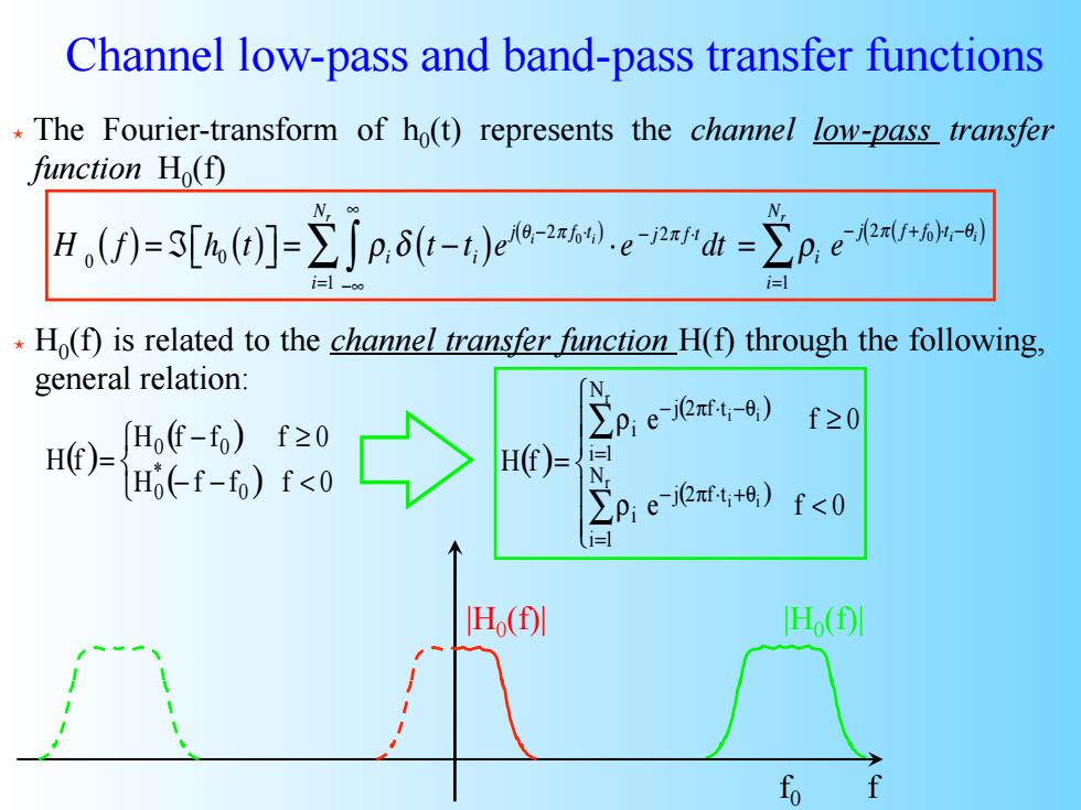
Channel low-pass and band-pass transfer functions The Fourier-transform of ho(t)represents the channel low-pass transfer function Ho(f) H)-3[(Jp.-t)p Ho(f)is related to the channel transfer function H(f)through the following, general relation: 66切e0 f20 Ho(-f-fo)f<0 H(f)= 1=] N Pejeπttt8)f<0 H()I 旧( fo
Channel low-pass and band-pass transfer functions The Fourier-transform of h0(t) represents the channel low-pass transfer function H0(f) H 0 ( f ) = ℑ h0 ⎡ (t) ⎣ ⎤⎦ = ρi δ t − t ( i)ej θi−2π f0⋅t ( i) ⋅ e − j 2π f ⋅t dt −∞ ∞ ∫ i=1 Nr ∑ = ρi e − j 2π f + f ( 0 )⋅ti−θ ( i) i=1 Nr ∑ H0(f) is related to the channel transfer function H(f) through the following, general relation: ( ) ( ) ( ) ⎩ ⎨ ⎧ − − < − ≥ = H f f f 0 H f f f 0 H f 0 * 0 0 0 f |H0(f)| |H0(f)| f0 ( ) ( ) ( ) ⎪ ⎪ ⎩ ⎪ ⎪ ⎨ ⎧ ρ < ρ ≥ = ∑ ∑ = − π ⋅ +θ = − π ⋅ −θ e f 0 e f 0 H f r i i r i i N i 1 j 2 f t i N i 1 j 2 f t i
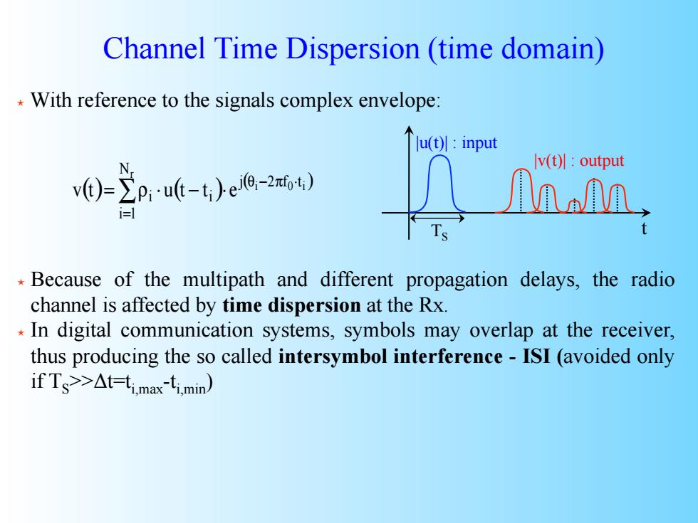
Channel Time Dispersion(time domain) With reference to the signals complex envelope: lu(t):input v(t):output 0-=2A6-ea- Because of the multipath and different propagation delays,the radio channel is affected by time dispersion at the Rx. In digital communication systems,symbols may overlap at the receiver, thus producing the so called intersymbol interference-ISI(avoided only ifTs>△t-t.max-t1min)
With reference to the signals complex envelope: Because of the multipath and different propagation delays, the radio channel is affected by time dispersion at the Rx. In digital communication systems, symbols may overlap at the receiver, thus producing the so called intersymbol interference - ISI (avoided only if TS>>Δt=ti,max-ti,min) t |u(t)| : input |v(t)| : output TS Channel Time Dispersion (time domain) ( ) ( ) ( ) ∑ = θ − π ⋅ = ρ ⋅ − ⋅ r i 0 i N i 1 j 2 f t i i v t u t t e