Group Project of Aircraft Design 上游充通大 Conceptual Design of an Amphibious Tactical Transport Aircraft Major: School of Aeronautics and Astronautics Name: Wang Meng 5124139010 Xu Yiran 5124139003 Ye Jiachen 5124139022 Zhang Pengyu 5124139016 Zheng Siyu 5124139005 Adviser: Dr.Song Wenbin 2015.7.5
Group Project of Aircraft Design Conceptual Design of an Amphibious Tactical Transport Aircraft Major: School of Aeronautics and Astronautics Name: Wang Meng 5124139010 Xu Yiran 5124139003 Ye Jiachen 5124139022 Zhang Pengyu 5124139016 Zheng Siyu 5124139005 Adviser: Dr. Song Wenbin 2015.7.5

Group Project of Aircraft Design Abstract Military transport aircraft has an important status in the national defense.Considering the serious situation of the Nansha Islands on the south ocean,we decide to design an amphibious tactical transport aircraft to apply to the national defense of south ocean.In this report,we will specifically design the layout,payload,wing,fuselage,boat,landing gear,tail wing,and choose a suitable kind of engine,and most excellent materials to make our aircraft better.In addition,we will analyze different performances and constantly adjust the parameters in order to have a better performance.And of course,the life-cycle cost analysis is also an important process as we would like to have the best economics.At last,we will make a comparison with other similar aircraft and give the model of our aircraft
Group Project of Aircraft Design Abstract Military transport aircraft has an important status in the national defense. Considering the serious situation of the Nansha Islands on the south ocean, we decide to design an amphibious tactical transport aircraft to apply to the national defense of south ocean. In this report, we will specifically design the layout, payload, wing, fuselage, boat, landing gear, tail wing, and choose a suitable kind of engine, and most excellent materials to make our aircraft better. In addition, we will analyze different performances and constantly adjust the parameters in order to have a better performance. And of course, the life-cycle cost analysis is also an important process as we would like to have the best economics. At last, we will make a comparison with other similar aircraft and give the model of our aircraft
Group Project of Aircraft Design Contents 1 National Defense....... ..1 2 Introduction of Transport Aircraft. 2 2.1 Brief Introduction and Classification 2 2.2 Civil Transport Planes......... .2 2.3 Abroad Transport Aircraft.... .6 2.4Seaplane .8 3 Primary Parameters Determination. 4 Initial layout......... 9 4.1 Introduction. 9 4.2 Airfoil.… .9 4.3 Fuselage.… 11 4.4 Tail Arrangement........ 12 4.5 Engine Placement....... 农 4.6 Landing Gear Layout....... 13 4.7 Initial Overall Layout..... 13 5 Preliminary Weight Estimation. 14 5.1 Introduction........ 14 5.2 Empty-weight Estimation. 15 5.3 Fuel Estimation...... 15 5.4 Weight Estimation Conclusion. 18 5.5 Wing loading Estimation........ 18 5.6 Thrust-to-weight Ratio............ .19 5.7 Synthetic Estimation of T/W and W/S. 20 5.8 The Conclusion of T/W and W/S.... 21 6 The Design of Fuselage....... 3 6.1 Introduction.… 22 6.2 Criteria.… 23 6.3 Terminology Definition.. 23 6.4 Detailed Design.… 24 6.5 Cockpit and Cabin...... 28 6.6Carg0D00r… 30 7 Boat Design.… 31 7.1 Hydrodynamic Layout..... 31 7.2 Principles of the Boat Design...... 32 7.3 Principal Dimension of Boat Body. 32 7.3 Step Design.… 33 7.4 Cross Section of the Boat. 33 7.5 Boat Shape................ 34 8 Wing Design… .35 8.1 Wing Shape Design................. .35
Group Project of Aircraft Design Contents 1 National Defense.............................................................................................................................. 1 2 Introduction of Transport Aircraft....................................................................................................2 2.1 Brief Introduction and Classification....................................................................................2 2.2 Civil Transport Planes...........................................................................................................2 2.3 Abroad Transport Aircraft..................................................................................................... 6 2.4 Seaplane.................................................................................................................................8 3 Primary Parameters Determination..................................................................................................8 4 Initial layout..................................................................................................................................... 9 4.1 Introduction........................................................................................................................... 9 4.2 Airfoil.................................................................................................................................... 9 4.3 Fuselage...............................................................................................................................11 4.4 Tail Arrangement.................................................................................................................12 4.5 Engine Placement................................................................................................................12 4.6 Landing Gear Layout.......................................................................................................... 13 4.7 Initial Overall Layout..........................................................................................................13 5 Preliminary Weight Estimation...................................................................................................... 14 5.1 Introduction......................................................................................................................... 14 5.2 Empty-weight Estimation................................................................................................... 15 5.3 Fuel Estimation................................................................................................................... 15 5.4 Weight Estimation Conclusion............................................................................................18 5.5 Wing loading Estimation.....................................................................................................18 5.6 Thrust-to-weight Ratio........................................................................................................19 5.7 Synthetic Estimation of T/W and W/S................................................................................20 5.8 The Conclusion of T/W and W/S........................................................................................21 6 The Design of Fuselage..................................................................................................................22 6.1 Introduction......................................................................................................................... 22 6.2 Criteria.................................................................................................................................23 6.3 Terminology Definition.......................................................................................................23 6.4 Detailed Design...................................................................................................................24 6.5 Cockpit and Cabin...............................................................................................................28 6.6 Cargo Door..........................................................................................................................30 7 Boat Design.................................................................................................................................... 31 7.1 Hydrodynamic Layout........................................................................................................ 31 7.2 Principles of the Boat Design..............................................................................................32 7.3 Principal Dimension of Boat Body.....................................................................................32 7.3 Step Design......................................................................................................................... 33 7.4 Cross Section of the Boat....................................................................................................33 7.5 Boat Shape...........................................................................................................................34 8 Wing Design...................................................................................................................................35 8.1 Wing Shape Design.............................................................................................................35
Group Project of Aircraft Design 8.2 Wing Geometry Optimization..... 41 9 Tail Geometry and Arrangement. 46 9.1 Tail Functions........ 46 9.2 Tail Arrangement............ 46 9.3 Horizontal Tail Parameters. 48 9.4 Vertical Tail Parameters. 51 9.5 Area of Tail 52 10 Engine. 53 10.1 Introduction 53 10.2 Choice of Engine Type. 54 10.3 Engine Installation...... 56 1 1 Landing gear.… 57 11.1 Landing Gear Arrangements. 少 11.2 Tire Sizing and Number.............. 58 l2 Refined Weight.… 59 12.1 Weight of Components.......... .59 12.2 Weight and Center of Gravity Estimation. 61 13 Lift and Drag Estimation.............. …62 13.1 Lift Estimation......... 62 13.2 Drag Estimation 64 14 Flight Performance....... 66 14.1 Takeoff Performance 67 14.2 Climb Performance. 68 14.3 Cruise Performance. 69 14.4 Landing Performance.......... 70 14.5 Summary...... 71 15 Hydrodynamic Performance........ 71 15.1 Force Analysis.......... 71 15.2 Takeoff Performance..... 73 16 Materials.… 77 16.1 Introduction. 77 16.2 Airframe Material Selection........ 79 16.3 Wing Material Selection.......... 79 16.4 Landing Gear Material Selection.... 80 17 Life-cycle Cost Analysis............ 81 17.1 Introduction. 81 17.2 RDT&E and Production Cost Analysis. 82 17.3 Operation and Maintenance Costs. 84 17.4 LCC Conclusion....... 86 18 Conclusion. 86 Acknowledgment. 88 Reference........ 88
Group Project of Aircraft Design 8.2 Wing Geometry Optimization.............................................................................................41 9 Tail Geometry and Arrangement....................................................................................................46 9.1 Tail Functions......................................................................................................................46 9.2 Tail Arrangement.................................................................................................................46 9.3 Horizontal Tail Parameters..................................................................................................48 9.4 Vertical Tail Parameters...................................................................................................... 51 9.5 Area of Tail..........................................................................................................................52 10 Engine...........................................................................................................................................53 10.1 Introduction....................................................................................................................... 53 10.2 Choice of Engine Type......................................................................................................54 10.3 Engine Installation............................................................................................................ 56 11 Landing gear.................................................................................................................................57 11.1 Landing Gear Arrangements............................................................................................. 57 11.2 Tire Sizing and Number.................................................................................................... 58 12 Refined Weight.............................................................................................................................59 12.1 Weight of Components......................................................................................................59 12.2 Weight and Center of Gravity Estimation.........................................................................61 13 Lift and Drag Estimation..............................................................................................................62 13.1 Lift Estimation.................................................................................................................. 62 13.2 Drag Estimation................................................................................................................ 64 14 Flight Performance.......................................................................................................................66 14.1 Takeoff Performance......................................................................................................... 67 14.2 Climb Performance........................................................................................................... 68 14.3 Cruise Performance...........................................................................................................69 14.4 Landing Performance........................................................................................................70 14.5 Summary........................................................................................................................... 71 15 Hydrodynamic Performance........................................................................................................ 71 15.1 Force Analysis...................................................................................................................71 15.2 Takeoff Performance......................................................................................................... 73 16 Materials.......................................................................................................................................77 16.1 Introduction....................................................................................................................... 77 16.2 Airframe Material Selection..............................................................................................79 16.3 Wing Material Selection....................................................................................................79 16.4 Landing Gear Material Selection......................................................................................80 17 Life-cycle Cost Analysis.............................................................................................................. 81 17.1 Introduction....................................................................................................................... 81 17.2 RDT&E and Production Cost Analysis............................................................................ 82 17.3 Operation and Maintenance Costs.................................................................................... 84 17.4 LCC Conclusion................................................................................................................86 18 Conclusion....................................................................................................................................86 Acknowledgment...............................................................................................................................88 Reference...........................................................................................................................................88
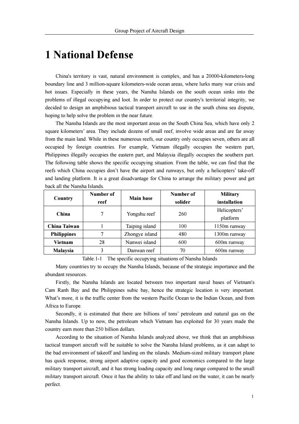
Group Project of Aircraft Design 1 National Defense China's territory is vast,natural environment is complex,and has a 20000-kilometers-long boundary line and 3 million-square kilometers-wide ocean areas,where lurks many war crisis and hot issues.Especially in these years,the Nansha Islands on the south ocean sinks into the problems of illegal occupying and loot.In order to protect our country's territorial integrity,we decided to design an amphibious tactical transport aircraft to use in the south china sea dispute, hoping to help solve the problem in the near future. The Nansha Islands are the most important areas on the South China Sea,which have only 2 square kilometers'area.They include dozens of small reef,involve wide areas and are far away from the main land.While in these numerous reefs,our country only occupies seven,others are all occupied by foreign countries.For example,Vietnam illegally occupies the western part, Philippines illegally occupies the eastern part,and Malaysia illegally occupies the southern part. The following table shows the specific occupying situation.From the table,we can find that the reefs which China occupies don't have the airport and runways,but only a helicopters'take-off and landing platform.It is a great disadvantage for China to arrange the military power and get back all the Nansha Islands. Number of Number of Military Country Main base reef solider installation China 7 Yongshu reef Helicopters' 260 platform China Taiwan Taiping island 100 1150m runway Philippines > Zhongye island 480 1300m runway Vietnam 28 Nanwei island 600 600m runway Malaysia 3 Danwan reef 70 600m runway Table.1-1 The specific occupying situations of Nansha Islands Many countries try to occupy the Nansha Islands,because of the strategic importance and the abundant resources. Firstly,the Nansha Islands are located between two important naval bases of Vietnam's Cam Ranh Bay and the Philippines subic bay,hence the strategic location is very important. What's more,it is the traffic center from the western Pacific Ocean to the Indian Ocean,and from Africa to Europe. Secondly,it is estimated that there are billions of tons'petroleum and natural gas on the Nansha Islands.Up to now,the petroleum which Vietnam has exploited for 30 years made the country earn more than 250 billion dollars. According to the situation of Nansha Islands analyzed above,we think that an amphibious tactical transport aircraft will be suitable to solve the Nansha Island problems,as it can adapt to the bad environment of takeoff and landing on the islands.Medium-sized military transport plane has quick response,strong airport adaptive capacity and good economics compared to the large military transport aircraft,and it has strong loading capacity and long range compared to the small military transport aircraft.Once it has the ability to take off and land on the water,it can be nearly perfect. 1
Group Project of Aircraft Design 1 1 National Defense China's territory is vast, natural environment is complex, and has a 20000-kilometers-long boundary line and 3 million-square kilometers-wide ocean areas, where lurks many war crisis and hot issues. Especially in these years, the Nansha Islands on the south ocean sinks into the problems of illegal occupying and loot. In order to protect our country's territorial integrity, we decided to design an amphibious tactical transport aircraft to use in the south china sea dispute, hoping to help solve the problem in the near future. The Nansha Islands are the most important areas on the South China Sea, which have only 2 square kilometers’ area. They include dozens of small reef, involve wide areas and are far away from the main land. While in these numerous reefs, our country only occupies seven, others are all occupied by foreign countries. For example, Vietnam illegally occupies the western part, Philippines illegally occupies the eastern part, and Malaysia illegally occupies the southern part. The following table shows the specific occupying situation. From the table, we can find that the reefs which China occupies don’t have the airport and runways, but only a helicopters’ take-off and landing platform. It is a great disadvantage for China to arrange the military power and get back all the Nansha Islands. Country Number of reef Main base Number of solider Military installation China 7 Yongshu reef 260 Helicopters’ platform China Taiwan 1 Taiping island 100 1150m runway Philippines 7 Zhongye island 480 1300m runway Vietnam 28 Nanwei island 600 600m runway Malaysia 3 Danwan reef 70 600m runway Table.1-1 The specific occupying situations of Nansha Islands Many countries try to occupy the Nansha Islands, because of the strategic importance and the abundant resources. Firstly, the Nansha Islands are located between two important naval bases of Vietnam's Cam Ranh Bay and the Philippines subic bay, hence the strategic location is very important. What’s more, it is the traffic center from the western Pacific Ocean to the Indian Ocean, and from Africa to Europe. Secondly, it is estimated that there are billions of tons’ petroleum and natural gas on the Nansha Islands. Up to now, the petroleum which Vietnam has exploited for 30 years made the country earn more than 250 billion dollars. According to the situation of Nansha Islands analyzed above, we think that an amphibious tactical transport aircraft will be suitable to solve the Nansha Island problems, as it can adapt to the bad environment of takeoff and landing on the islands. Medium-sized military transport plane has quick response, strong airport adaptive capacity and good economics compared to the large military transport aircraft, and it has strong loading capacity and long range compared to the small military transport aircraft. Once it has the ability to take off and land on the water, it can be nearly perfect
Group Project of Aircraft Design Firstly,as the Nansha Island include dozens of small reefs,the range is wide and the distance to the mainland is far,it is difficult for China to protect the territorial sovereignty.Because the operational radius of action of a common fighter is about 1000km,and the largest range is about 3000m,the far end of Nansha is almost the limitation of the j10.Hence,it is very necessary for the support of transport aircraft with air refueling ability. Secondly,because of the special geographical situation,the transport aircraft should have the ability to take off of land on water.As mentioned before,other countries have all constructed the runway and airport on their occupied islands,while China has only a helicopter platform.Hence, if the plane is amphibious,it can still reach the reef without the runway. In a word,the amphibious tactical transport aircraft can be widely used according to China's national defense.So our design is significant and important to the country's safety. 2 Introduction of Transport Aircraft 2.1 Brief Introduction and Classification Military transport aircraft can be defined in terms of their range capability as strategic transport aircraft or tactical transport aircraft.Strategic transport aircraft has a great power of capability whose take-off weight can be more than 150 tons with a payload of over 40 tons.Its air-range is more than 4000 km.To get huge capability and wide air-range,strategic transport aircraft sacrifices maneuverability which requires longer distance when taking off as well as landing.So it can only flies between large or medium airport with concrete runways far away from the battlefield.Tactical transport aircraft,though with take-off weight lower than 150 tons,has better maneuverability which qualified it for taking off and landing in short unprepared runways. So tactical transport aircraft is welcomed in the battlefront. In recent years,America and Russia and some other countries have seen a tendency in the transport aircraft development.Military transport aircraft should has an adequate size and maneuverability rather than a large capability like C-5 and An-224.So it is time to develop new type of medium tactical transport aircraft which can also carry more than traditional one. 2.2 Civil Transport Planes 2.2.1Y-30 Y-30 appeared in the 2014 Zhuhai air show,which was only a model but supposed to serve in the army by the year of 2020.The transport plane is still in the stage of conceptual design and will turn into full scale development phase in about two years.Y-30 is a high-wing plane with high horizontal tail and a large sterm port,which is a traditional configuration.The weight of future mainstream transport plane,The Y-30 is equipped with four turboprop engines,of which the power is estimated to be 3,782 KW.The aim of Y-30 is to adapt to accommodate main battle tanks 2
Group Project of Aircraft Design 2 Firstly, as the Nansha Island include dozens of small reefs, the range is wide and the distance to the mainland is far, it is difficult for China to protect the territorial sovereignty. Because the operational radius of action of a common fighter is about 1000km, and the largest range is about 3000m, the far end of Nansha is almost the limitation of the j10. Hence, it is very necessary for the support of transport aircraft with air refueling ability. Secondly, because of the special geographical situation, the transport aircraft should have the ability to take off of land on water. As mentioned before, other countries have all constructed the runway and airport on their occupied islands, while China has only a helicopter platform. Hence, if the plane is amphibious, it can still reach the reef without the runway. In a word, the amphibious tactical transport aircraft can be widely used according to China’s national defense. So our design is significant and important to the country’s safety. 2 Introduction of Transport Aircraft 2.1 Brief Introduction and Classification Military transport aircraft can be defined in terms of their range capability as strategic transport aircraft or tactical transport aircraft. Strategic transport aircraft has a great power of capability whose take-off weight can be more than 150 tons with a payload of over 40 tons. Its air-range is more than 4000 km. To get huge capability and wide air-range, strategic transport aircraft sacrifices maneuverability which requires longer distance when taking off as well as landing. So it can only flies between large or medium airport with concrete runways far away from the battlefield. Tactical transport aircraft, though with take-off weight lower than 150 tons, has better maneuverability which qualified it for taking off and landing in short unprepared runways. So tactical transport aircraft is welcomed in the battlefront. In recent years, America and Russia and some other countries have seen a tendency in the transport aircraft development. Military transport aircraft should has an adequate size and maneuverability rather than a large capability like C-5 and An-224. So it is time to develop new type of medium tactical transport aircraft which can also carry more than traditional one. 2.2 Civil Transport Planes 2.2.1 Y-30 Y-30 appeared in the 2014 Zhuhai air show, which was only a model but supposed to serve in the army by the year of 2020. The transport plane is still in the stage of conceptual design and will turn into full scale development phase in about two years. Y-30 is a high-wing plane with high horizontal tail and a large sterm port, which is a traditional configuration. The weight of future mainstream transport plane, The Y-30 is equipped with four turboprop engines, of which the power is estimated to be 3,782 KW. The aim of Y-30 is to adapt to accommodate main battle tanks
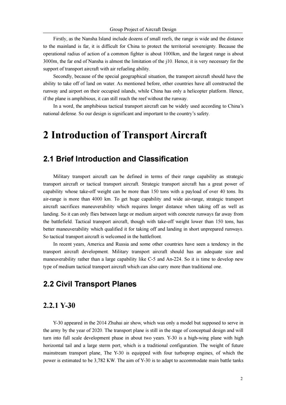
Group Project of Aircraft Design and other equipment with larger size.Y-30 has a maximum endurance of over 12 hours,the take-off distance of less than 1,200 meters,landing distance of less than 1,100 meters and can carry more than 110 soldiers.Compared with C-130,the biggest difference in appearance is the high horizontal tail which requires higher rigidity of the vertical tail and also increases the weight but reduces aerodynamic interference.The sweptback vertical tail configuration reduces the area of horizontal tail,reducing the drag,which is widely used in modern transport plane design.This type of transport plane is designed for the new generation of armored car and gunship,which demand larger volume than the existing Y-9 and Y-8 can offer. Fig.2-1 The model of Y-30 2.2.2Y-9 (1)Background Since Y-8 plane first flew in 1975,it has derived nearly 30 diversification with continuous innovation.In order to meet the command of development of military transportation,Y-9 was born at the right moment,which is meant to replace Y-8 as the new mainstream medium tactical transport plane.Since it was developed,its designers have been aimed at serialization and mufti-function from anti-submarine warfare,AEW,export,to air tanker. (2)Configuration Design Semi-Monique pressurized fuselage,up-warp rear fuselage,open-back warehouse gate, high-wing,single rudder,wing-mounted engine configuration was chosen as the basic configuration for the Y-9,which contributes to better control ability and better flight performances. In order to acquire favourable performance,four WJ-6C turboprop engines of 3800 kW are equipped as well as six-bladed composite propellers with large sweep-back angle,leading to good performances in high temperature and altitude.It can carry 98 soldiers within one flight. (3)Structure In order to meet the need for large weight and long service time,the designers optimize the wings,fuselage,and the landing gear according to the damage tolerance and durability rule.Y-9 is composed of three parts,namely,the front,the mid,and the end.The fuselage contains cockpit and warehouse,of which both are booster airtight cabin.A side boarding gate is set for the flight 3
Group Project of Aircraft Design 3 and other equipment with larger size. Y-30 has a maximum endurance of over 12 hours, the take-off distance of less than 1,200 meters, landing distance of less than 1,100 meters and can carry more than 110 soldiers. Compared with C-130, the biggest difference in appearance is the high horizontal tail which requires higher rigidity of the vertical tail and also increases the weight but reduces aerodynamic interference. The sweptback vertical tail configuration reduces the area of horizontal tail, reducing the drag, which is widely used in modern transport plane design. This type of transport plane is designed for the new generation of armored car and gunship, which demand larger volume than the existing Y-9 and Y-8 can offer. Fig.2-1 The model of Y-30 2.2.2 Y-9 (1) Background Since Y-8 plane first flew in 1975, it has derived nearly 30 diversification with continuous innovation. In order to meet the command of development of military transportation, Y-9 was born at the right moment, which is meant to replace Y-8 as the new mainstream medium tactical transport plane. Since it was developed, its designers have been aimed at serialization and mufti-function from anti-submarine warfare, AEW, export, to air tanker. (2) Configuration Design Semi-Monique pressurized fuselage, up-warp rear fuselage, open-back warehouse gate, high-wing, single rudder, wing-mounted engine configuration was chosen as the basic configuration for the Y-9, which contributes to better control ability and better flight performances. In order to acquire favourable performance, four WJ-6C turboprop engines of 3800 kW are equipped as well as six-bladed composite propellers with large sweep-back angle, leading to good performances in high temperature and altitude. It can carry 98 soldiers within one flight. (3) Structure In order to meet the need for large weight and long service time, the designers optimize the wings, fuselage, and the landing gear according to the damage tolerance and durability rule. Y-9 is composed of three parts, namely, the front, the mid, and the end. The fuselage contains cockpit and warehouse, of which both are booster airtight cabin. A side boarding gate is set for the flight
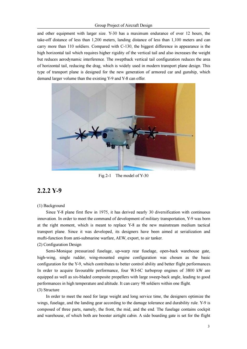
Group Project of Aircraft Design crew in the cockpit as well as a emergency exit in the warehouse in case of emergency situations. Back-open design is a common idea for this new transport plane and two auxiliary tanks are equipped in the mid part of the fuselage beneath the floor. Fig.2-2 Y-9 transport plane 2.2.3Y-8 Y-8 transport plane was first designed from 1970 to 1975,imitating the Ann 12 by the Soviet Union,and is now the main transport plane in the air force.Y-8 is the basic type with a number of variants for different demands such as early warning,civil use and UAV.The functions include paradrop,airborne,transport,lifesaving and offshore operation. (1)Structure Y-8 adopts straight cantilever high wing,double beam box-type structure and low resistance laminar airfoil.Wings are composed of center wing,center-outer wing and outer wing.The installation angle is 4,and center-outer has a dihedral angle of 1 to center wing,while outer wing has a anhedral angle of 3 to center wing,which makes the plane look like a sea gull and contributes to great performances in bumpy air.Double stitched retrogressive flap is adopted for high-lift device,outside of which is equipped with differential ailerons. The fuselage is divided into four parts,namely,the front,the mid,the back,and the tail.The front part is cockpit for pilots,navigators,communication messagers and mechanician.The nose is framed organic glass which is easier for the navigator to observe.The mid part is the cargo cabin, with auxiliary fuel tanks under the floor,occupying 123.3 m3.The back part is equipped with warming and air-condition system and it is connected with the seal tail part with aimers'seats. (2)Propulsion system Y-8 transport plane is equipped with four WJ-6 turboprop engines,with autofeathering and automatic pitch propeller J17-G13,with single power up to 3,120 Kw.Its service time has been lengthened to 3,000 hours from the original 300 hours.In 1982,improvement was achieved by increasing the power to 3,350Kw and reducing fuel consumption.The core technical measures contain an increase in turbine inlet temperature by 40C,and in rotate speed by 2%.The cooling gas circuit is improved with air-cooling blades in the first stage. 4
Group Project of Aircraft Design 4 crew in the cockpit as well as a emergency exit in the warehouse in case of emergency situations. Back-open design is a common idea for this new transport plane and two auxiliary tanks are equipped in the mid part of the fuselage beneath the floor. Fig.2-2 Y-9 transport plane 2.2.3 Y-8 Y-8 transport plane was first designed from 1970 to 1975, imitating the Ann 12 by the Soviet Union, and is now the main transport plane in the air force. Y-8 is the basic type with a number of variants for different demands such as early warning, civil use and UAV. The functions include paradrop, airborne, transport, lifesaving and offshore operation. (1) Structure Y-8 adopts straight cantilever high wing, double beam box-type structure and low resistance laminar airfoil. Wings are composed of center wing, center-outer wing and outer wing. The installation angle is 4°, and center-outer has a dihedral angle of 1°to center wing, while outer wing has a anhedral angle of 3°to center wing, which makes the plane look like a sea gull and contributes to great performances in bumpy air. Double stitched retrogressive flap is adopted for high-lift device, outside of which is equipped with differential ailerons. The fuselage is divided into four parts, namely, the front, the mid, the back, and the tail. The front part is cockpit for pilots, navigators, communication messagers and mechanician. The nose is framed organic glass which is easier for the navigator to observe. The mid part is the cargo cabin, with auxiliary fuel tanks under the floor, occupying 123.3 m³ . The back part is equipped with warming and air-condition system and it is connected with the seal tail part with aimers’seats. (2) Propulsion system Y-8 transport plane is equipped with four WJ-6 turboprop engines, with autofeathering and automatic pitch propeller J17-G13, with single power up to 3,120 Kw. Its service time has been lengthened to 3,000 hours from the original 300 hours. In 1982, improvement was achieved by increasing the power to 3,350Kw and reducing fuel consumption. The core technical measures contain an increase in turbine inlet temperature by 40℃, and in rotate speed by 2%. The cooling gas circuit is improved with air-cooling blades in the first stage
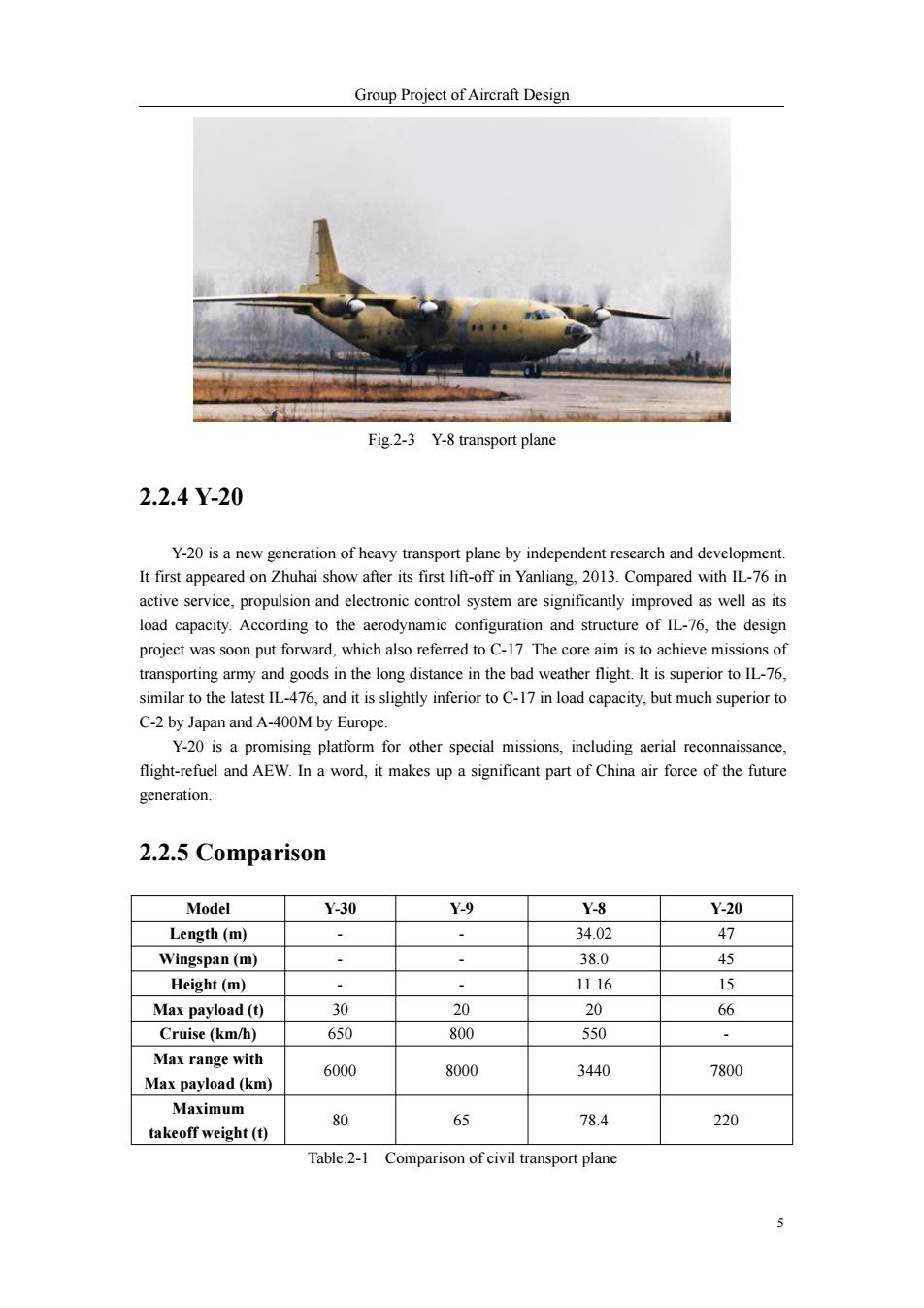
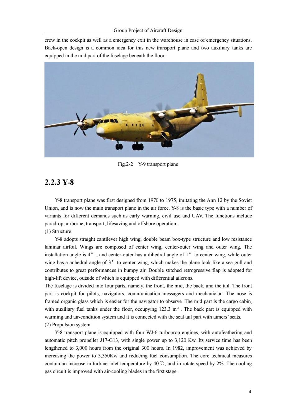
Group Project of Aircraft Design Fig.2-3 Y-8 transport plane 2.2.4Y-20 Y-20 is a new generation of heavy transport plane by independent research and development. It first appeared on Zhuhai show after its first lift-off in Yanliang,2013.Compared with IL-76 in active service,propulsion and electronic control system are significantly improved as well as its load capacity.According to the aerodynamic configuration and structure of IL-76,the design project was soon put forward,which also referred to C-17.The core aim is to achieve missions of transporting army and goods in the long distance in the bad weather flight.It is superior to IL-76, similar to the latest IL-476,and it is slightly inferior to C-17 in load capacity,but much superior to C-2 by Japan and A-400M by Europe. Y-20 is a promising platform for other special missions,including aerial reconnaissance, flight-refuel and AEW.In a word,it makes up a significant part of China air force of the future generation. 2.2.5 Comparison Model Y-30 Y-9 Y-8 Y-20 Length (m) 、 34.02 47 Wingspan(m) 38.0 45 Height(m) 11.16 15 Max payload (t) 30 20 20 66 Cruise(km/h) 650 800 550 Max range with 6000 8000 3440 7800 Max payload (km) Maximum 80 65 78.4 220 takeoff weight(t) Table.2-1 Comparison of civil transport plane 5
Group Project of Aircraft Design 5 Fig.2-3 Y-8 transport plane 2.2.4 Y-20 Y-20 is a new generation of heavy transport plane by independent research and development. It first appeared on Zhuhai show after its first lift-off in Yanliang, 2013. Compared with IL-76 in active service, propulsion and electronic control system are significantly improved as well as its load capacity. According to the aerodynamic configuration and structure of IL-76, the design project was soon put forward, which also referred to C-17. The core aim is to achieve missions of transporting army and goods in the long distance in the bad weather flight. It is superior to IL-76, similar to the latest IL-476, and it is slightly inferior to C-17 in load capacity, but much superior to C-2 by Japan and A-400M by Europe. Y-20 is a promising platform for other special missions, including aerial reconnaissance, flight-refuel and AEW. In a word, it makes up a significant part of China air force of the future generation. 2.2.5 Comparison Model Y-30 Y-9 Y-8 Y-20 Length (m) - - 34.02 47 Wingspan (m) - - 38.0 45 Height (m) - - 11.16 15 Max payload (t) 30 20 20 66 Cruise (km/h) 650 800 550 - Max range with Max payload (km) 6000 8000 3440 7800 Maximum takeoff weight (t) 80 65 78.4 220 Table.2-1 Comparison of civil transport plane
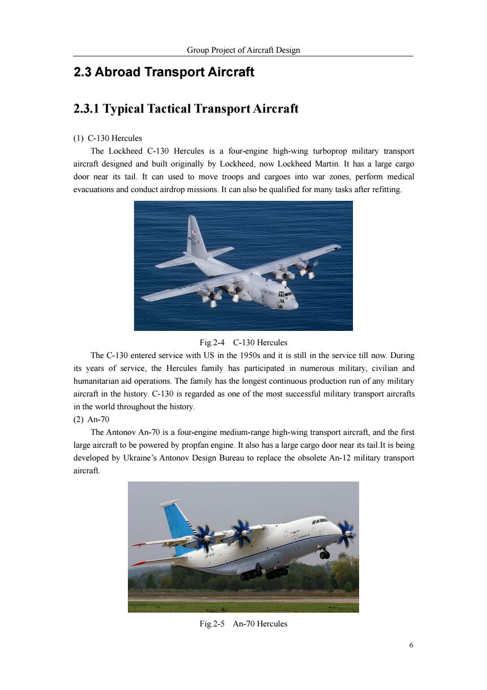
Group Project of Aircraft Design 2.3 Abroad Transport Aircraft 2.3.1 Typical Tactical Transport Aircraft (1)C-130 Hercules The Lockheed C-130 Hercules is a four-engine high-wing turboprop military transport aircraft designed and built originally by Lockheed,now Lockheed Martin.It has a large cargo door near its tail.It can used to move troops and cargoes into war zones,perform medical evacuations and conduct airdrop missions.It can also be qualified for many tasks after refitting. Fig.2-4 C-130 Hercules The C-130 entered service with US in the 1950s and it is still in the service till now.During its years of service,the Hercules family has participated in numerous military,civilian and humanitarian aid operations.The family has the longest continuous production run of any military aircraft in the history.C-130 is regarded as one of the most successful military transport aircrafts in the world throughout the history (2)An-70 The Antonov An-70 is a four-engine medium-range high-wing transport aircraft,and the first large aircraft to be powered by propfan engine.It also has a large cargo door near its tail.It is being developed by Ukraine's Antonov Design Bureau to replace the obsolete An-12 military transport aircraft. Fig.2-5 An-70 Hercules 6
Group Project of Aircraft Design 6 2.3 Abroad Transport Aircraft 2.3.1 Typical Tactical Transport Aircraft (1) C-130 Hercules The Lockheed C-130 Hercules is a four-engine high-wing turboprop military transport aircraft designed and built originally by Lockheed, now Lockheed Martin. It has a large cargo door near its tail. It can used to move troops and cargoes into war zones, perform medical evacuations and conduct airdrop missions. It can also be qualified for many tasks after refitting. Fig.2-4 C-130 Hercules The C-130 entered service with US in the 1950s and it is still in the service till now. During its years of service, the Hercules family has participated in numerous military, civilian and humanitarian aid operations. The family has the longest continuous production run of any military aircraft in the history. C-130 is regarded as one of the most successful military transport aircrafts in the world throughout the history. (2) An-70 The Antonov An-70 is a four-engine medium-range high-wing transport aircraft, and the first large aircraft to be powered by propfan engine. It also has a large cargo door near its tail.It is being developed by Ukraine’s Antonov Design Bureau to replace the obsolete An-12 military transport aircraft. Fig.2-5 An-70 Hercules