2018/3/11 图上产文大华 Overview of Lectures 国上清大学 0.Overview 14/15 Performance(a,b) 16.Aircraft certification Overall confiauration 17.Aviation economics 18.System integration and d weight estimation coafiauraticn management Aircraft Design Fuselage design 19.Multidisciplinary design (飞行器设计) 6/7/8 Aerodynamic design(a,b,c) ootimization .h a and ing 20.Military aircraft design-overview 21.Environmental issues 10.Landing gear and Aircraft systems 22.Desian skills Wenbin Song 11.Power plant School of Aeronautics and Astronautics 12.Stability and control Shanghai Jiao Tong University 13.Loads,materials and structures o r nd 0171 Soor an0 Overview 圈上活大坐 Landing gear examples 圆上清道大坐 Basic Design Requirements A350XMw Tasks in Landing Gear Design Landing Gear Arrangements Main Design Parameters Principles for Deciding Parameters Number of tyres and dimension Shock absorbers and Retraction Geometry "The essential intermediary between the aeroplane catastrophe"-Conway,Landing Gear Design,1958 Main Landing Gear components 国上洋大坐 Basic Requirements for Landing Gear Design 园上海发大坐 dem Gompatr-218 Maintain the position of the airplane during take-off and landing Correct down locations for taxing,take-off and landing -Turning radil,stability,roll angle The tires and shock strut must be just the right size Retracted to the correct location Sufficient space for retracted landing gear 1f 1
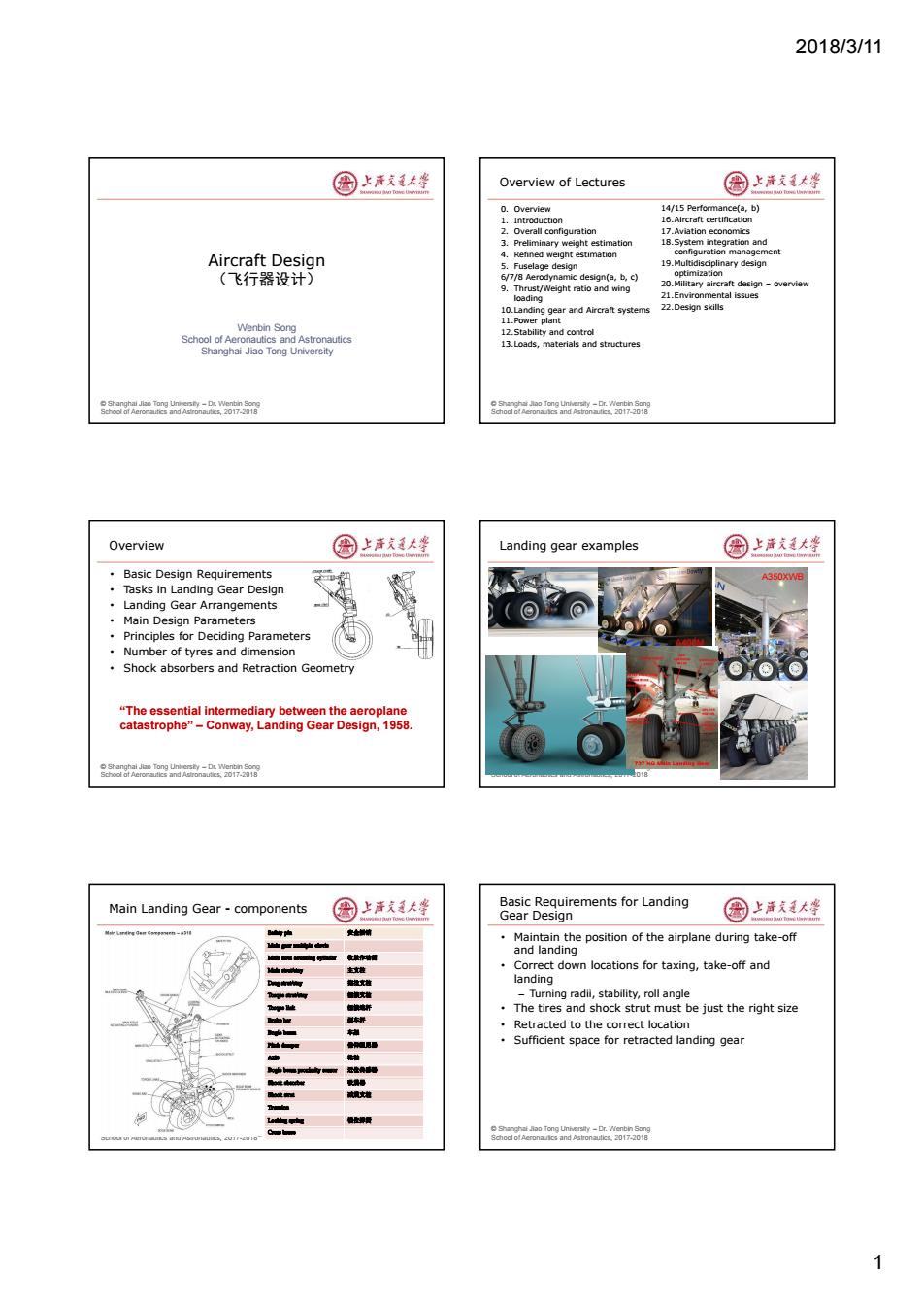
2018/3/11 1 © Shanghai Jiao Tong University – Dr. Wenbin Song School of Aeronautics and Astronautics, 2017-2018 Aircraft Design (飞行器设计) Wenbin Song School of Aeronautics and Astronautics Shanghai Jiao Tong University © Shanghai Jiao Tong University – Dr. Wenbin Song School of Aeronautics and Astronautics, 2017-2018 Overview of Lectures 0. Overview 1. Introduction 2. Overall configuration 3. Preliminary weight estimation 4. Refined weight estimation 5. Fuselage design 6/7/8 Aerodynamic design(a, b, c) 9. Thrust/Weight ratio and wing loading 10.Landing gear and Aircraft systems 11.Power plant 12.Stability and control 13.Loads, materials and structures 14/15 Performance(a, b) 16.Aircraft certification 17.Aviation economics 18.System integration and configuration management 19.Multidisciplinary design optimization 20.Military aircraft design – overview 21.Environmental issues 22.Design skills © Shanghai Jiao Tong University – Dr. Wenbin Song School of Aeronautics and Astronautics, 2017-2018 Overview • Basic Design Requirements • Tasks in Landing Gear Design • Landing Gear Arrangements • Main Design Parameters • Principles for Deciding Parameters • Number of tyres and dimension • Shock absorbers and Retraction Geometry “The essential intermediary between the aeroplane catastrophe” – Conway, Landing Gear Design, 1958. © Shanghai Jiao Tong University – Dr. Wenbin Song School of Aeronautics and Astronautics, 2017-2018 Landing gear examples A400M A350XWB © Shanghai Jiao Tong University – Dr. Wenbin Song School of Aeronautics and Astronautics, 2017-2018 Main Landing Gear - components © Shanghai Jiao Tong University – Dr. Wenbin Song School of Aeronautics and Astronautics, 2017-2018 Basic Requirements for Landing Gear Design • Maintain the position of the airplane during take-off and landing • Correct down locations for taxing, take-off and landing – Turning radii, stability, roll angle • The tires and shock strut must be just the right size • Retracted to the correct location • Sufficient space for retracted landing gear
2018/3/11 Challenges in Landing Gear Design 圈上声文大学 Tasks and Objectives in Landing Gear Design 国上清大学 Attachment fitting adapted to the A/C structure ·Tasks: Geometry Adapted Min.ove ral din vith the L/G in the up to the aircraft -Requirements analysis Adapted tire retraction path -Integration with aircraft and configuration C.G.location) -Weight and loads,shock absorber Optimized Loads On landing -Kinematics(retraction and deployment) And Performance On rolling During retraction and extension -Cost Analysis Design Objectives and Constraints Required static strength -Minimum weight Dimensions -Maximum component strength High reliability Optimized ·Safety Low cost Operation 。Reliability -Overall aircraft integration Airfield compatibility Reduced Overall Cou High op ating endurance Easy maintenance More Detailed Description of Tasks 圈上活大坐 Historical Data 国上活大等 Type (tricycle,tail gear,bicycle,etc) Fixed(faired,or un-faired),or retractable,partially B:-J818W retractable 8 ·Height B7888N8 Wheel base 6%7 Wheel track 0.0500 The distance between main gear and c.g. Strut diameter 0.040 Tire sizing (diameter,width) Landing gear compartment (retracted) ·Load on each strut 3% GD Ean (d eRoskam'sreri Design Weighs Vo 00200 TOGW Ratio of la eagaea2-w58 _f/M96SC.html Landing Gear Arrangements 国上洋大峰 Landing Gear Selection vs Aircraft Weight 园上海发大坐 启三点式,touchdownspeed<12okm/h Aireraft Weight Landing Gear Selection sailplane B52 Four wheel Quadricycle 400000t 81436kg ngle main ge 250000b. 11398kg Two main wheel per strut/four B47 A380 150000b 68038kg wheel bogey Multi-bogey ain wheel 50000b 22680kg 满三点式,240一28okm/h Single main neel per strut 2
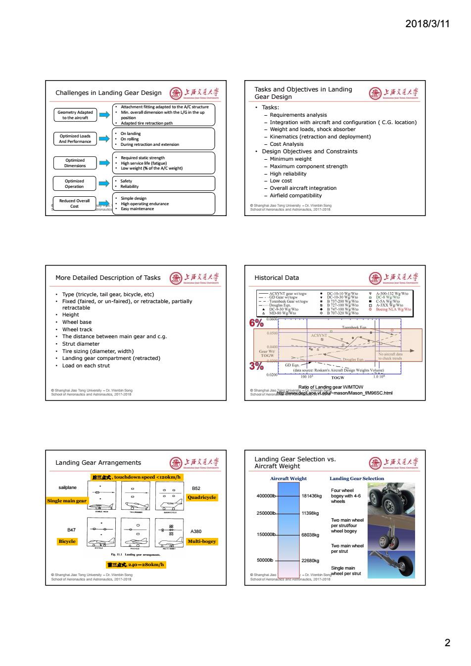
2018/3/11 2 © Shanghai Jiao Tong University – Dr. Wenbin Song School of Aeronautics and Astronautics, 2017-2018 Challenges in Landing Gear Design Geometry Adapted to the aircraft Optimized Loads And Performance Optimized Dimensions Optimized Operation Reduced Overall Cost • Attachment fitting adapted to the A/C structure • Min. overall dimension with the L/G in the up position • Adapted tire retraction path • On landing • On rolling • During retraction and extension • Required static strength • High service life (fatigue) • Low weight (% of the A/C weight) • Safety • Reliability • Simple design • High operating endurance • Easy maintenance © Shanghai Jiao Tong University – Dr. Wenbin Song School of Aeronautics and Astronautics, 2017-2018 Tasks and Objectives in Landing Gear Design • Tasks: – Requirements analysis – Integration with aircraft and configuration ( C.G. location) – Weight and loads, shock absorber – Kinematics (retraction and deployment) – Cost Analysis • Design Objectives and Constraints – Minimum weight – Maximum component strength – High reliability – Low cost – Overall aircraft integration – Airfield compatibility © Shanghai Jiao Tong University – Dr. Wenbin Song School of Aeronautics and Astronautics, 2017-2018 More Detailed Description of Tasks • Type (tricycle, tail gear, bicycle, etc) • Fixed (faired, or un-faired), or retractable, partially retractable • Height • Wheel base • Wheel track • The distance between main gear and c.g. • Strut diameter • Tire sizing (diameter, width) • Landing gear compartment (retracted) • Load on each strut © Shanghai Jiao Tong University – Dr. Wenbin Song School of Aeronautics and Astronautics, 2017-2018 Historical Data Ratio of Landing gear W/MTOW http://www.dept.aoe.vt.edu/~mason/Mason_f/M96SC.html © Shanghai Jiao Tong University – Dr. Wenbin Song School of Aeronautics and Astronautics, 2017-2018 Landing Gear Arrangements 后三点式 , touchdown speed <120km/h 前三点式, 240-280km/h Single main gear Bicycle Quadricycle Multi-bogey B47 sailplane B52 A380 © Shanghai Jiao Tong University – Dr. Wenbin Song School of Aeronautics and Astronautics, 2017-2018 Landing Gear Selection vs. Aircraft Weight 50000lb Single main wheel per strut 150000lb Two main wheel per strut 250000lb 400000lb Four wheel bogey with 4-6 wheels Two main wheel per strut/four wheel bogey 22680kg 68038kg 11398kg 181436kg Aircraft Weight Landing Gear Selection
2018/3/11 C.G.Locations 图上声大学 Typical Landing Gear Geometry Parameters 国上清大坐 >C.G.locations are important for positioning of the landing ” gear CG Six main geometry >Can be estimated from component weights parameters ground angle-p(停机角) b一前,主轮距 tip back angle-Y(防倒位角) wheel base-B(住轮距) tail clearance angle-8( 地角) Height一高度 Ref:land_3 o r nd 0171 Soor an0 Ground Angle- 国上活大峰 Tip Clearance Angle- 国上道大坐 Definition:the angle between level base line of Definition:the angle between runway surface and a aircraft and runway surface plane passing through main gear touchdown point and To reduce takeoff field length tangent to the bottom of aft fuselage ·Typical values0°w4 Influence on aft fuselage flow characteristics Determined from AOA for landing a Takeolf=a incidence alanding a incidence y=a Takeoff-aincidence =C landing-V-mnctdence rAer 8oa6o0e四k-a88 Tipback Angle -Y 图上洋大峰 前,主轮距-b和主起落架高度-H 园上海发大坐 Tipback angle is the maximum aircraft nose-up angle ·When deciding b with the tail touching the ground and strut fully -To make sure nose gear doesn't carry too much or too extended little load 防倒立角should be max(tail clearance angle,15) b =(0.3-0.4)L fuselage Or -85%-92%of weight supported by main gear ·防倒立角should be max(tail clearance angle+(1°~2°), When deciding H 15) -Constrained by where the main gear is retracted into ·r Sufficient ground clearance ·max(tail clearance angle-+(1°w2°)[former Soviet Union] 3
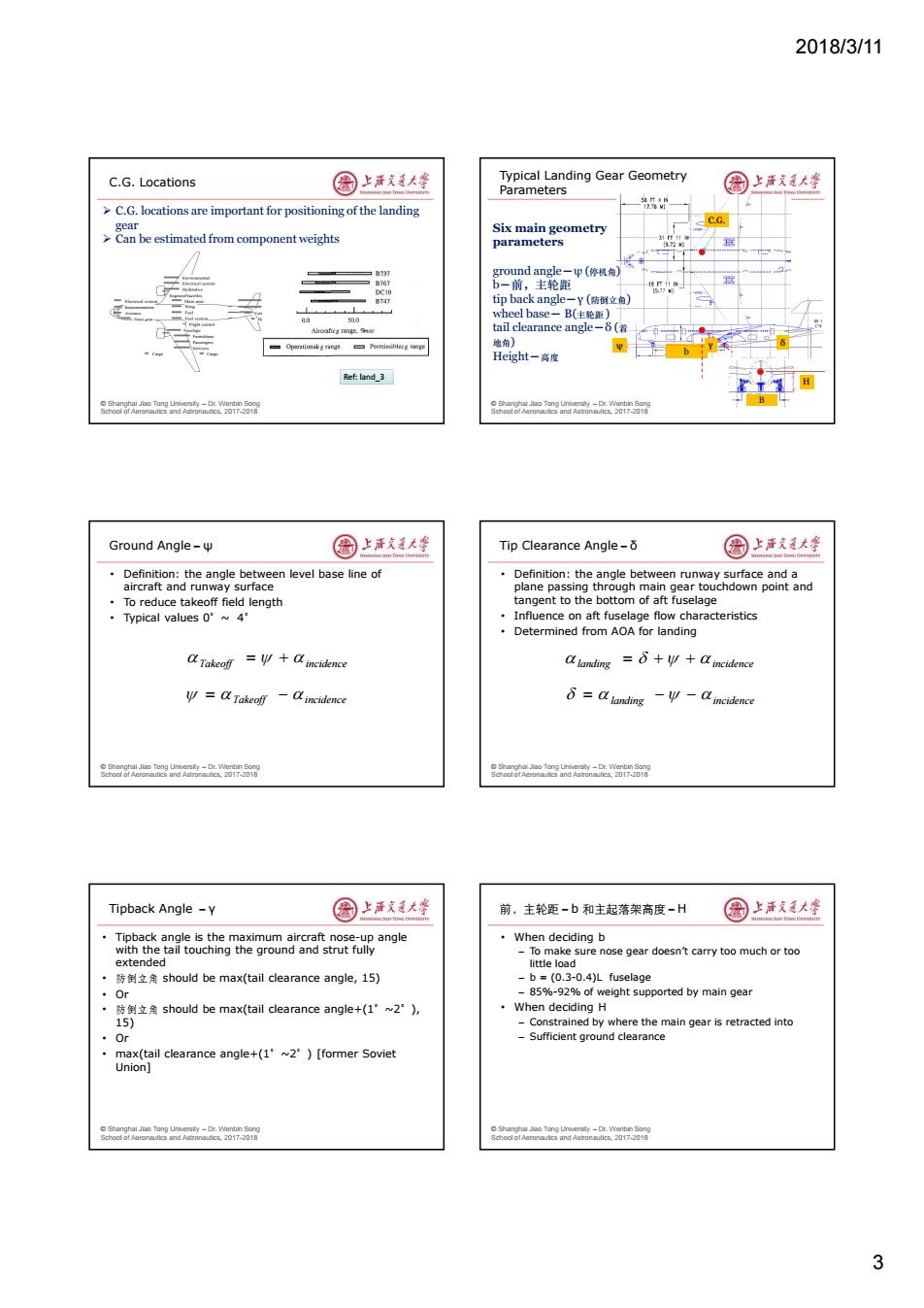
2018/3/11 3 © Shanghai Jiao Tong University – Dr. Wenbin Song School of Aeronautics and Astronautics, 2017-2018 C.G. Locations C.G. locations are important for positioning of the landing gear Can be estimated from component weights Ref: land_3 © Shanghai Jiao Tong University – Dr. Wenbin Song School of Aeronautics and Astronautics, 2017-2018 Typical Landing Gear Geometry Parameters C.G. B Six main geometry parameters ground angle-ψ (停机角) b-前,主轮距 tip back angle-γ (防倒立角) wheel base- B(主轮距 ) tail clearance angle-δ (着 地角) Height-高度 b ψ γ δ H © Shanghai Jiao Tong University – Dr. Wenbin Song School of Aeronautics and Astronautics, 2017-2018 Ground Angle-ψ • Definition: the angle between level base line of aircraft and runway surface • To reduce takeoff field length • Typical values 0°~ 4° Takeoff incidence Takeoff incidence © Shanghai Jiao Tong University – Dr. Wenbin Song School of Aeronautics and Astronautics, 2017-2018 Tip Clearance Angle-δ • Definition: the angle between runway surface and a plane passing through main gear touchdown point and tangent to the bottom of aft fuselage • Influence on aft fuselage flow characteristics • Determined from AOA for landing landing incidence landing incidence © Shanghai Jiao Tong University – Dr. Wenbin Song School of Aeronautics and Astronautics, 2017-2018 Tipback Angle -γ • Tipback angle is the maximum aircraft nose-up angle with the tail touching the ground and strut fully extended • 防倒立角 should be max(tail clearance angle, 15) • Or • 防倒立角 should be max(tail clearance angle+(1°~2°), 15) • Or • max(tail clearance angle+(1°~2°) [former Soviet Union] © Shanghai Jiao Tong University – Dr. Wenbin Song School of Aeronautics and Astronautics, 2017-2018 前,主轮距-b 和主起落架高度-H • When deciding b – To make sure nose gear doesn’t carry too much or too little load – b = (0.3-0.4)L fuselage – 85%-92% of weight supported by main gear • When deciding H – Constrained by where the main gear is retracted into – Sufficient ground clearance
2018/3/11 Wheel Base-B 园上清大华 Parameters for Taildragger Landing Gear 国上清大学 ·Main criteria -To prevent side tip 2hbu Side slipfriction coefficient B2 Va-Wu 4=0.85 -Constrained by wing structure or fuselage diameter o r nd 0171 Soor an0 Tire Sizing 国上清文大些 Tire Selection 圆上洋式美大李 Tires are sized to carry the weight of the aircraft Tires are selected based on sizing results from -Main tires carry about 85%-92%of aircraft weight manufacture's catalogue Nose tires carry the rest of static load but are subject to higher dynamic loads during landing Main wheels sizing table Ma (Max长LoaL=W兰 A Mf Mi Load-w管 W-Weight on Whed Nose tires can be assumed to be about 6o-100%of the size of the main tires rAer 8oa6o0e四k-a88 Tire Pressure and Tire Contact Area 圈上洋天通大学 Shock Absorbers 图上活大坐 Load carried by internal pressure Tires are very limited in absorbing shock caused by a bad landing Methods:solid spring to Oleo shock absorber Ww-PA A,=23网(得-R 南 令9在号共 4
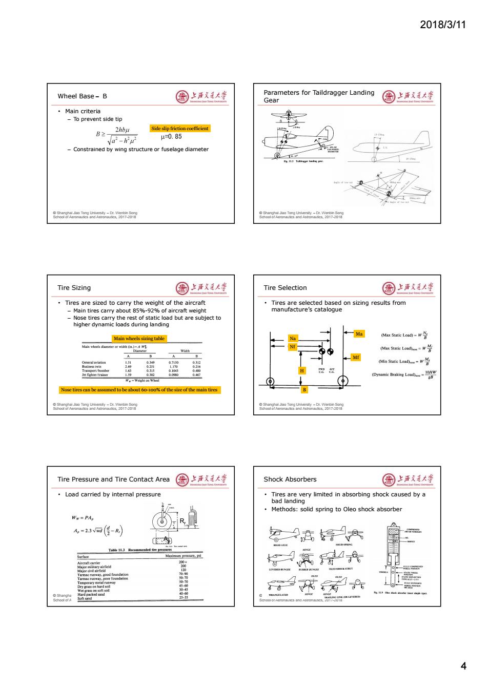
2018/3/11 4 © Shanghai Jiao Tong University – Dr. Wenbin Song School of Aeronautics and Astronautics, 2017-2018 Wheel Base- B • Main criteria – To prevent side tip – Constrained by wing structure or fuselage diameter Side slip friction coefficient © Shanghai Jiao Tong University – Dr. Wenbin Song School of Aeronautics and Astronautics, 2017-2018 Parameters for Taildragger Landing Gear © Shanghai Jiao Tong University – Dr. Wenbin Song School of Aeronautics and Astronautics, 2017-2018 Tire Sizing • Tires are sized to carry the weight of the aircraft – Main tires carry about 85%-92% of aircraft weight – Nose tires carry the rest of static load but are subject to higher dynamic loads during landing Main wheels sizing table Nose tires can be assumed to be about 60-100% of the size of the main tires © Shanghai Jiao Tong University – Dr. Wenbin Song School of Aeronautics and Astronautics, 2017-2018 Tire Selection • Tires are selected based on sizing results from manufacture’s catalogue Na Nf Ma Mf H B © Shanghai Jiao Tong University – Dr. Wenbin Song School of Aeronautics and Astronautics, 2017-2018 Tire Pressure and Tire Contact Area • Load carried by internal pressure Ap Rr © Shanghai Jiao Tong University – Dr. Wenbin Song School of Aeronautics and Astronautics, 2017-2018 Shock Absorbers • Tires are very limited in absorbing shock caused by a bad landing • Methods: solid spring to Oleo shock absorber
2018/3/11 Analysis of Shock Absorber 国上唐美大坐 Retraction of Landing Gear 国上清大学 The total energy of aircraft at the instant of Design of mechanical links ① touchdown is given by ·Space requirements Wv ·Complexity E= -+(w-L)(S+S) ·Reliability 2g ·Weight where Wis the aircraft weight,Vis the sink speed,L is the lift,S,is tire ·Fairing deflection S is shock absorber stroke(unknown variables) ⑤ The kinetic energy capacity of shock absorber and tire must be equal to E. nSNW +n.SNW=WV2 -+(W-L)+S) 2g o r nd 0171 Soor an0 Gear Retraction Geometry 国上活大峰 ACN-PCN Convention 国上活支廷大峰 ACN-PCN:Aircraft/Pavement Classification Number -A simple system of categorizing and reporting the runway's capabilities to support aircraft If ACNX inch ing gea back D Structural dynamic response of the airframe,f significant Tip bock freveanon -Load conditions Touch-doun -Tests ·Limit drop tests to poro before end of nina h wing dotkc r the ond due to the 5
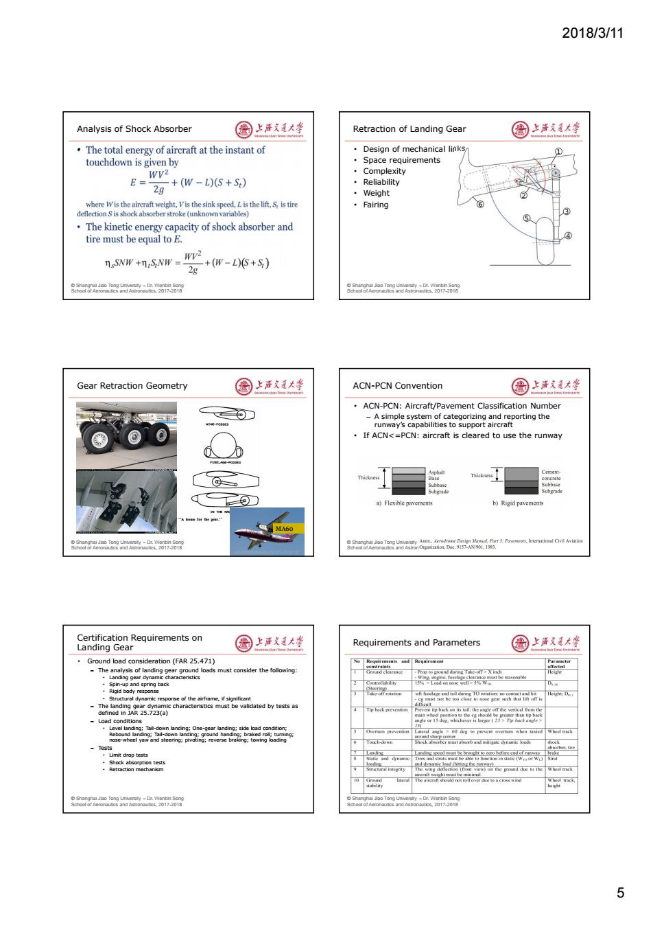
2018/3/11 5 © Shanghai Jiao Tong University – Dr. Wenbin Song School of Aeronautics and Astronautics, 2017-2018 Analysis of Shock Absorber • © Shanghai Jiao Tong University – Dr. Wenbin Song School of Aeronautics and Astronautics, 2017-2018 Retraction of Landing Gear • Design of mechanical links • Space requirements • Complexity • Reliability • Weight • Fairing © Shanghai Jiao Tong University – Dr. Wenbin Song School of Aeronautics and Astronautics, 2017-2018 Gear Retraction Geometry MA60 © Shanghai Jiao Tong University – Dr. Wenbin Song School of Aeronautics and Astronautics, 2017-2018 ACN-PCN Convention • ACN-PCN: Aircraft/Pavement Classification Number – A simple system of categorizing and reporting the runway’s capabilities to support aircraft • If ACN<=PCN: aircraft is cleared to use the runway © Shanghai Jiao Tong University – Dr. Wenbin Song School of Aeronautics and Astronautics, 2017-2018 Certification Requirements on Landing Gear • Ground load consideration (FAR 25.471) – The analysis of landing gear ground loads must consider the following: • Landing gear dynamic characteristics • Spin-up and spring back • Rigid body response • Structural dynamic response of the airframe, if significant – The landing gear dynamic characteristics must be validated by tests as defined in JAR 25.723(a) – Load conditions • Level landing; Tail-down landing; One-gear landing; side load condition; Rebound landing; Tail-down landing; ground handing; braked roll; turning; nose-wheel yaw and steering; pivoting; reverse braking; towing loading – Tests • Limit drop tests • Shock absorption tests • Retraction mechanism © Shanghai Jiao Tong University – Dr. Wenbin Song School of Aeronautics and Astronautics, 2017-2018 Requirements and Parameters
2018/3/11 Landing Gear of the Future 圆上活大学 Other Aircraft Subsystems 国上清大学 ·Electrical driven? Other major aircraft systems ·Low noise gear Fuel system Stitched composite doors -Avionics Electrical systems Hydraulics -Auxiliary Power System ·Readings: -What are other major aircraft subsystems? -How they function? -What are the trend for future technological developments? -Implications of these new trend on design? o r nd 01701 Summary 国上活大峰 国上清道大坐 Design Requirements and Tasks in Landing Gear Design Types of Landing Gear Landing Gear Design Principles Landing Gear Parameters Tire Sizing Procedures Shock Absorbers and Gear Retraction Geometry Backup slides Notes:Copyright of relevant pictures belong to their original owner eagaea2-w58 8oa6o0e四k-a88 More Landing Gear in Picture 圈上洋文通大学 An225 C-5 6
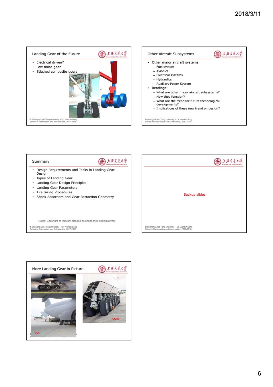
2018/3/11 6 © Shanghai Jiao Tong University – Dr. Wenbin Song School of Aeronautics and Astronautics, 2017-2018 Landing Gear of the Future • Electrical driven? • Low noise gear • Stitched composite doors © Shanghai Jiao Tong University – Dr. Wenbin Song School of Aeronautics and Astronautics, 2017-2018 Other Aircraft Subsystems • Other major aircraft systems – Fuel system – Avionics – Electrical systems – Hydraulics – Auxiliary Power System • Readings: – What are other major aircraft subsystems? – How they function? – What are the trend for future technological developments? – Implications of these new trend on design? © Shanghai Jiao Tong University – Dr. Wenbin Song School of Aeronautics and Astronautics, 2017-2018 Summary • Design Requirements and Tasks in Landing Gear Design • Types of Landing Gear • Landing Gear Design Principles • Landing Gear Parameters • Tire Sizing Procedures • Shock Absorbers and Gear Retraction Geometry Notes: Copyright of relevant pictures belong to their original owner © Shanghai Jiao Tong University – Dr. Wenbin Song School of Aeronautics and Astronautics, 2017-2018 Backup slides © Shanghai Jiao Tong University – Dr. Wenbin Song School of Aeronautics and Astronautics, 2017-2018 More Landing Gear in Picture An225 C-5