
2018/2/26 圆上活大学 Overview of Lectures 国上清大学 0.Overview 14/15 Performance(a,b) 16.Aircraft certification 2.Overall configuration(a.b) 17.Aviation economics weight estin ion 18.System integration and estimation configuration management Aircraft Design 5.Fuselage design 19.Multidisciplinary design 6/7/8 Aerodynamic design(a,b) ootimization (飞行器设计) .nd ng 20.Military aircraft design-overview 21.Environmental issues 10.Landing gear and Aircraft systems 22.Desian skills Wenbin Song 11.Power plant School of Aeronautics and Astronautics 12.Stability and control Shanghai Jiao Tong University 13.Loads,materials and structures o r nd 0171 Aircraft Overall Configuration 国上活大峰 Possible Aircraft Configurations 圆上清道大坐 Configuration of major components Fuselage -Wing -Engines Tails Gear ro surfaces Stability Installation of Aircraft Systems haegplantandasytens rcarriage Control Systems -Cockpit and Instrument SOngr 0 taao Evolution of Civil Transport Aircraft Configurations 圆上活天道大学 园上海发大坐 Improved aerodynamics(drag reduction and load control) New materials and structural analysis Manufacturina/Assembly methods Lighter and more efficient engines Increased reliability ·Integrated systems Modem avionics and computer control technology Integrated CAE methods to design Comet1 Boeing787 SECTION I AIRCRAFT CONFIGURATIONS 1
2018/2/26 1 © Shanghai Jiao Tong University – Dr. Wenbin Song School of Aeronautics and Astronautics, 2017-2018 Aircraft Design (飞行器设计) Wenbin Song School of Aeronautics and Astronautics Shanghai Jiao Tong University © Shanghai Jiao Tong University – Dr. Wenbin Song School of Aeronautics and Astronautics, 2017-2018 Overview of Lectures 0. Overview 1. Introduction 2. Overall configuration(a, b) 3. Preliminary weight estimation 4. Refined weight estimation 5. Fuselage design 6/7/8 Aerodynamic design(a, b) 9. Thrust/Weight ratio and wing loading 10.Landing gear and Aircraft systems 11.Power plant 12.Stability and control 13.Loads, materials and structures 14/15 Performance(a, b) 16.Aircraft certification 17.Aviation economics 18.System integration and configuration management 19.Multidisciplinary design optimization 20.Military aircraft design – overview 21.Environmental issues 22.Design skills © Shanghai Jiao Tong University – Dr. Wenbin Song School of Aeronautics and Astronautics, 2017-2018 Aircraft Overall Configuration • Configuration of major components – Fuselage – Wing – Engines – Tails – Landing Gear – C.G. and Balances • Weight distribution • Control surfaces • Stability • Installation of Aircraft Systems – Powerplant and fuel systems – Undercarriage – Control Systems – Cockpit and Instrument 3 © Shanghai Jiao Tong University – Dr. Wenbin Song School of Aeronautics and Astronautics, 2017-2018 Possible Aircraft Configurations Rutan|X36|Tornado| cessna172|Bulldog|A380 MD82|Concord|F22Rapter http://www.airliners.net © Shanghai Jiao Tong University – Dr. Wenbin Song School of Aeronautics and Astronautics, 2017-2018 Evolution of Civil Transport Aircraft Configurations • Improved aerodynamics (drag reduction and load control) • New materials and structural analysis • Manufacturing/Assembly methods • Lighter and more efficient engines • Increased reliability • Integrated systems • Modern avionics and computer control technology • Integrated CAE methods to design 50+ years Comet 1 Boeing787 © Shanghai Jiao Tong University – Dr. Wenbin Song School of Aeronautics and Astronautics, 2017-2018 AIRCRAFT CONFIGURATIONS SECTION I
2018/2/26 Selection of Aircraft Configurations 园上声克大学 Aircraft Systems 国上清大学 Aerodynamic configuration,positioning of wing,tail,control winglet surfaces,and power plant Functions of each components coekpit wing -Wing is the main lift generating device -Tails and control surfaces provide balance and control Verticaltail Landing gear,retracted or not -Power plant,type,thrust,installation,etc Landing gear aa6as8vaeetaepenontethnialea Style,Market appeal,Convention,Customer's altitude udder Fuel systems Horizontaltail engines slat o r nd 0171 Soor an0 Inputs and Disciplines in 国上清文大些 Aircraft Balance-forces and Configuration Design moments 园上活道大整 ·Inputs: Mission profile Disciplines: -Design objectives and constraint: -Cost analysis For aircraft with natural stability LIFT -Technology base -Resour -Aerodynamics schedule Structural design Engine -Performance Stability and control WEIGHT Overall configuration of the aircraft 8oa6o0e四k-a88 Aircraft Balance-forces and moments 国上洋大坐 Possible Layout 国上洋大学 Based on the relative position of wing tails,and control surfaces For aircraft with natural instability Conventional:horizontal tail aft of wing -Canard(聘式):small wing ahead of wing -Tailless:no horizontal tail -Three-surface configuration:front wing,wing,and tail Blended Wing Body (BWB) 2
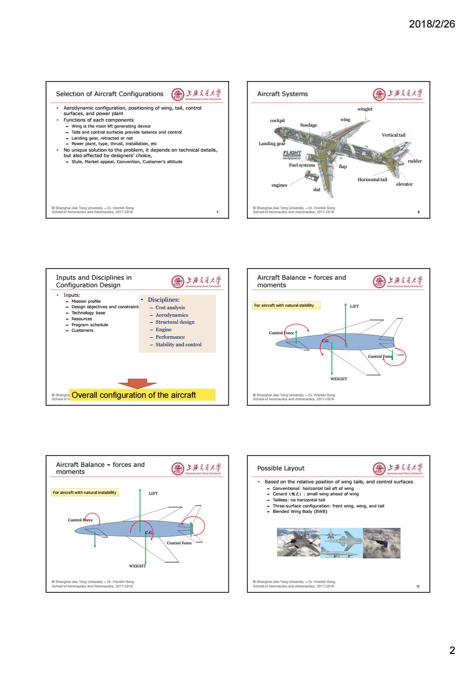
2018/2/26 2 © Shanghai Jiao Tong University – Dr. Wenbin Song School of Aeronautics and Astronautics, 2017-2018 Selection of Aircraft Configurations • Aerodynamic configuration, positioning of wing, tail, control surfaces, and power plant • Functions of each components – Wing is the main lift generating device – Tails and control surfaces provide balance and control – Landing gear, retracted or not – Power plant, type, thrust, installation, etc • No unique solution to the problem, it depends on technical details, but also affected by designers’ choice, – Style, Market appeal, Convention, Customer’s altitude 7 © Shanghai Jiao Tong University – Dr. Wenbin Song School of Aeronautics and Astronautics, 2017-2018 Aircraft Systems 8 engines wing winglet Vertical tail Horizontal tail elevator rudder fuselage cockpit Landing gear flap slat Fuel systems © Shanghai Jiao Tong University – Dr. Wenbin Song School of Aeronautics and Astronautics, 2017-2018 Inputs and Disciplines in Configuration Design • Inputs: – Mission profile – Design objectives and constraints – Technology base – Resources – Program schedule – Customers • Disciplines: – Cost analysis – Aerodynamics – Structural design – Engine – Performance – Stability and control Overall configuration of the aircraft © Shanghai Jiao Tong University – Dr. Wenbin Song School of Aeronautics and Astronautics, 2017-2018 Aircraft Balance – forces and moments C.G. LIFT Control Force Control Force WEIGHT For aircraft with natural stability © Shanghai Jiao Tong University – Dr. Wenbin Song School of Aeronautics and Astronautics, 2017-2018 Aircraft Balance – forces and moments C.G. LIFT Control Force Control Force WEIGHT For aircraft with natural instability © Shanghai Jiao Tong University – Dr. Wenbin Song School of Aeronautics and Astronautics, 2017-2018 Possible Layout • Based on the relative position of wing tails, and control surfaces – Conventional: horizontal tail aft of wing – Canard(鸭式): small wing ahead of wing – Tailless: no horizontal tail – Three-surface configuration: front wing, wing, and tail – Blended Wing Body (BWB) 12
2018/2/26 Aerodynamic efficiency of two aircraft 国上活大坐 Conventional Layout 国上清大学 ·Two ·Conventional layout dramatically oted by m nost military and civil aircrant gStors horizontal tail Wing span wetted areas are the two Fig.3.4 Dees apect ratlo dng? Soor an0 Canard Configuration(鹃式布局) 圈上活大坐 Canard Configuration(II) 国上大坐 -First used by Wright brother ·Two types of canard -Canard allows for reduced trim drag,especially for supersonic flight -Control-canard,operates at zero angle of attack and carry little of the -Close coupled canard-wing reduces necessary wing twist (favorable aircraft's weight washout from canard) -Lifting-canard,both wing and canard produce lift to support aircraft -Enabled by modern control technology weight -Tandem wing design-the size of canard comparable to the wing Eurofighter Typhoon Saab JAS 39B Gripen J-10 OMAC Laser 3D0 p 8oa6o0e四k-a88 Canard configuration (III) 图上洋大峰 Tailless Configuration 国上洋大学 Disadvantages er the lowest weight and drag of ny 。 -Canards have poor stealth performance ural stability, Sizing and positioning of canard is difficult -Possible adverse flow disturbances to flow over upper surface of the Typically balanced using flaps wing Balance efficiency is not good due to small arm conventional tail,therefore requiring Pictures from ntern Northrop YB-49 Prototype AeroVironment Pathfinder B-2 3
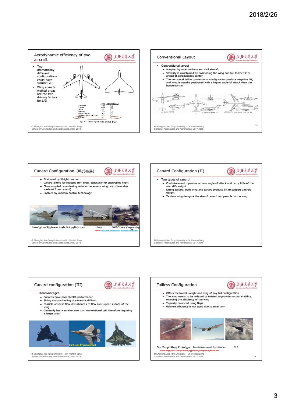
2018/2/26 3 © Shanghai Jiao Tong University – Dr. Wenbin Song School of Aeronautics and Astronautics, 2017-2018 Aerodynamic efficiency of two aircraft • Two dramatically different configurations could have similar L/D • Wing span & wetted areas are the two driving factors for L/D © Shanghai Jiao Tong University – Dr. Wenbin Song School of Aeronautics and Astronautics, 2017-2018 Conventional Layout • Conventional layout – Adopted by most military and civil aircraft – Stability is maintained by positioning the wing and tail to keep C.G. ahead of aerodynamic center – The horizontal tail in conventional configuration produce negative lift, and wing is usually positioned with a higher angle of attack than the horizontal tail 14 © Shanghai Jiao Tong University – Dr. Wenbin Song School of Aeronautics and Astronautics, 2017-2018 Canard Configuration(鸭式布局) – First used by Wright brother – Canard allows for reduced trim drag, especially for supersonic flight – Close coupled canard-wing reduces necessary wing twist (favorable washout from canard) – Enabled by modern control technology 15 Eurofighter Typhoon Saab JAS 39B Gripen J-10 Source: http://www.wikepedia.com, http://oea.larc.nasa.gov/ OMAC Laser 300 prototype © Shanghai Jiao Tong University – Dr. Wenbin Song School of Aeronautics and Astronautics, 2017-2018 Canard Configuration (II) • Two types of canard – Control-canard, operates at zero angle of attack and carry little of the aircraft’s weight – Lifting-canard, both wing and canard produce lift to support aircraft weight – Tandem wing design – the size of canard comparable to the wing © Shanghai Jiao Tong University – Dr. Wenbin Song School of Aeronautics and Astronautics, 2017-2018 Canard configuration (III) • Disadvantages – Canards have poor stealth performance – Sizing and positioning of canard is difficult – Possible adverse flow disturbances to flow over upper surface of the wing – Generally has a smaller arm than conventional tail, therefore requiring a larger area Pictures from Internet 17 © Shanghai Jiao Tong University – Dr. Wenbin Song School of Aeronautics and Astronautics, 2017-2018 Tailless Configuration – Offers the lowest weight and drag of any tail configuration – The wing needs to be reflexed or twisted to provide natural stability, reducing the efficiency of the wing – Typically balanced using flaps – Balance efficiency is not good due to small arm 18 Source: http://www.desktopaero.com/appliedaero/configuration/tailless.html Northrop YB-49 Prototype AeroVironment Pathfinder B-2
2018/2/26 Pros and Cons of Tailless Configuration 园上声克大学 Three-surface configuration (三翼面布局) 国上清大学 Reduced structural weight Good stealth characteristics trol char Disadvantages indude Incressed structural weight due to structural complexity 人 o r nd 0171 Soor an0 Three surface configuration(II) 圈上活文大些 Forward sweep aircraft 园上活道大整 is not widely used,but this is F-15S/MDT验迁机 Su-47 NASA AD-1 (span=6.1m) eagaea2-w58 8oa6o0e四k-a88 Forward swept wings on X-29 国上清大学 Blended Wing Body /Hybrid wing body 国上洋大学 Inherently unstable due to positive bending-torsion coupling (wash-in) due use of structural strength Unidirectional composite can be used to stiffen the wing structure performance while at the same time reduce its wash-in response Active controls can also be used to change the load distribution on the wing to further alleviate the susceptibility to an Aeroelastic -Reduced wave drag for failure both transonic and supersonic flight NASA X48B scaled model test flight Pictures from intemet B-21 4
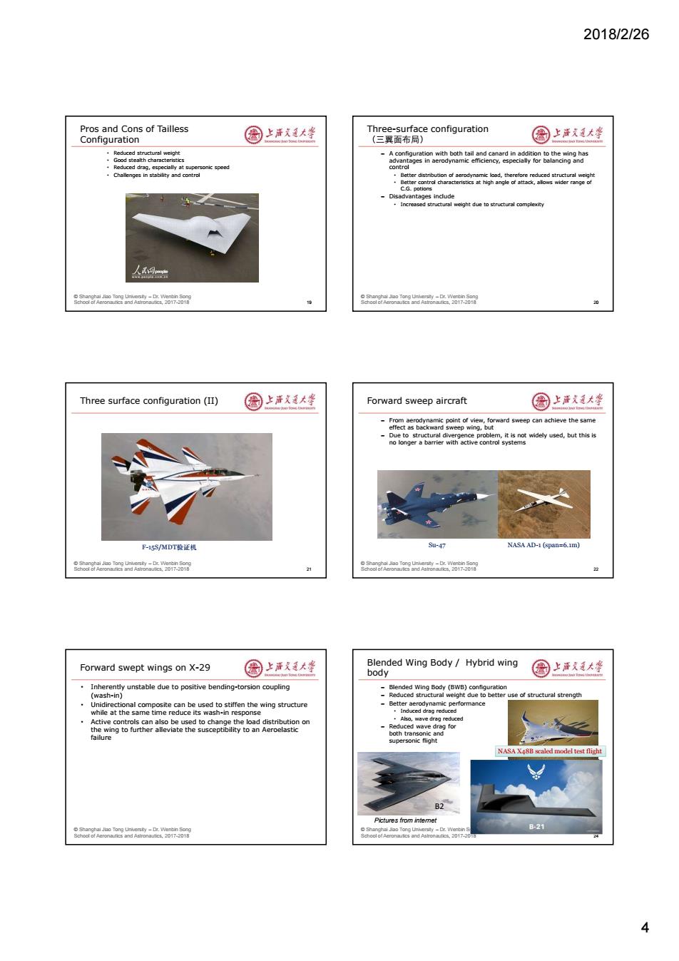
2018/2/26 4 © Shanghai Jiao Tong University – Dr. Wenbin Song School of Aeronautics and Astronautics, 2017-2018 Pros and Cons of Tailless Configuration • Reduced structural weight • Good stealth characteristics • Reduced drag, especially at supersonic speed • Challenges in stability and control 19 © Shanghai Jiao Tong University – Dr. Wenbin Song School of Aeronautics and Astronautics, 2017-2018 Three-surface configuration (三翼面布局) – A configuration with both tail and canard in addition to the wing has advantages in aerodynamic efficiency, especially for balancing and control • Better distribution of aerodynamic load, therefore reduced structural weight • Better control characteristics at high angle of attack, allows wider range of C.G. potions – Disadvantages include • Increased structural weight due to structural complexity 20 © Shanghai Jiao Tong University – Dr. Wenbin Song School of Aeronautics and Astronautics, 2017-2018 Three surface configuration (II) 21 F-15S/MDT验证机 © Shanghai Jiao Tong University – Dr. Wenbin Song School of Aeronautics and Astronautics, 2017-2018 Forward sweep aircraft – From aerodynamic point of view, forward sweep can achieve the same effect as backward sweep wing, but – Due to structural divergence problem, it is not widely used, but this is no longer a barrier with active control systems 22 Su-47 NASA AD-1 (span=6.1m) © Shanghai Jiao Tong University – Dr. Wenbin Song School of Aeronautics and Astronautics, 2017-2018 Forward swept wings on X-29 • Inherently unstable due to positive bending-torsion coupling (wash-in) • Unidirectional composite can be used to stiffen the wing structure while at the same time reduce its wash-in response • Active controls can also be used to change the load distribution on the wing to further alleviate the susceptibility to an Aeroelastic failure © Shanghai Jiao Tong University – Dr. Wenbin Song School of Aeronautics and Astronautics, 2017-2018 Blended Wing Body / Hybrid wing body – Blended Wing Body (BWB) configuration – Reduced structural weight due to better use of structural strength – Better aerodynamic performance • Induced drag reduced • Also, wave drag reduced – Reduced wave drag for both transonic and supersonic flight 24 NASA X48B scaled model test flight B2 Pictures from internet
2018/2/26 Oblique wing(斜翼布局) 国上活大坐 Some Other Aircraft Examples 国上清大学 -Oblique wing configuration is beneficial in reducing drag -Often seen on UAVs -Reduced structural weight by maintaining Just one axis -With specialized mission definition Pictures from intemet 99长g望44 2017-2018 Wing Configuration 圆上清文大些 Vertical Positioning of Wing 圆上洋廷大蜂 Wina planform definition Wing sections-airfoil aerodynamics Vertical positions of wing relative to the fuselage High-w ing Mtid-wing To be discussed in aerodynamics section Lou-wing Low Wing Configuration 国上清大学 High Wing Configuration 园上海发大坐 Use for most passenger aircraft Most common for military transport aircraft Wing central box structure embedded into fuselage without Fuselage close to the ground for easier loading/unloading sacrificing space Structural benefit if wina is not passina through fuselage landing gear installed in the wing,shortening the length use of very large flaps to realize short takeoff and landing se to the ground,better for replacement and Less risk of engine absorbing flying rocks and debris at unimproved fields Fuselage needs to be strengthened to support landing gear A320 AD-225 C-130 5
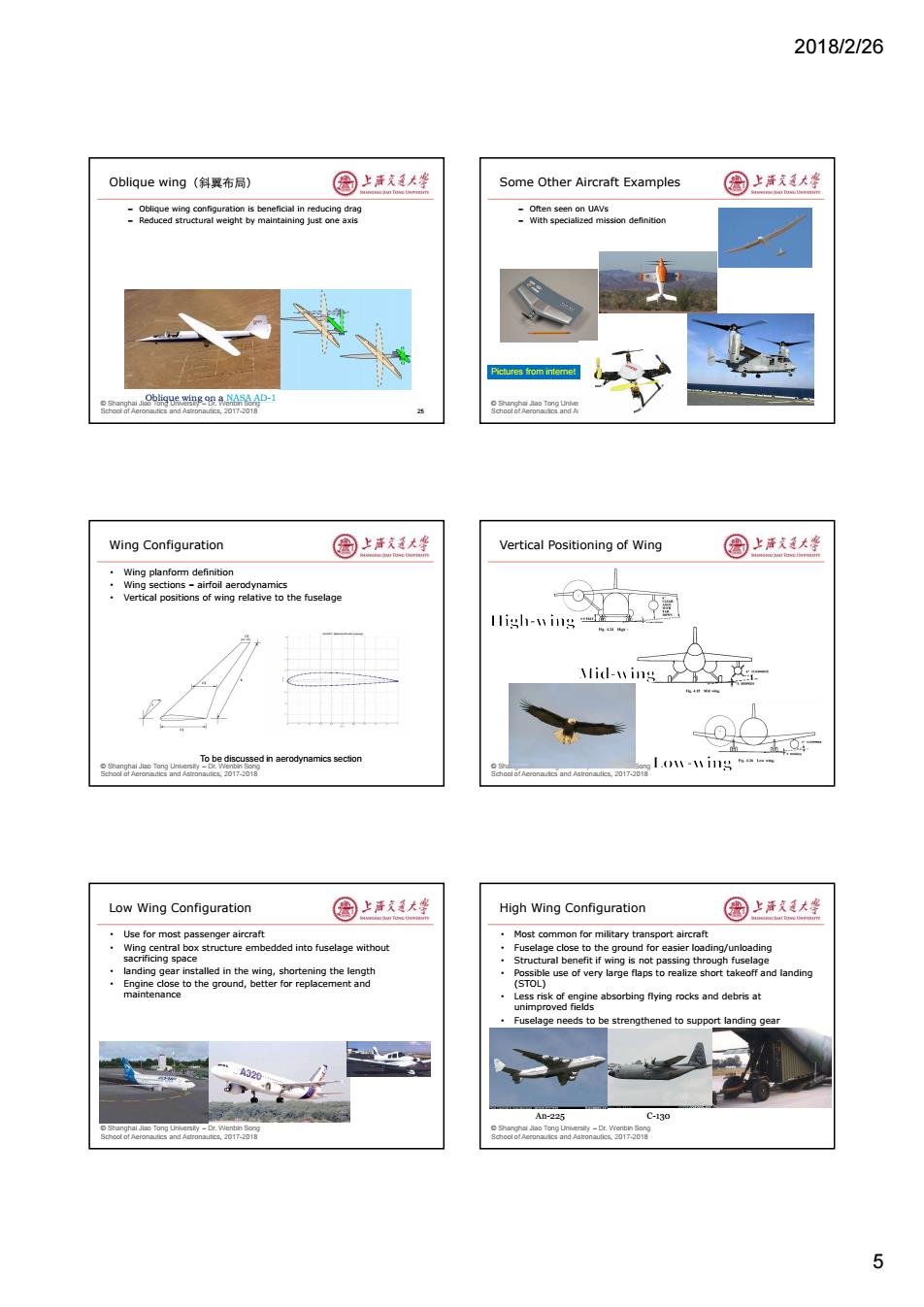
2018/2/26 5 © Shanghai Jiao Tong University – Dr. Wenbin Song School of Aeronautics and Astronautics, 2017-2018 Oblique wing(斜翼布局) – Oblique wing configuration is beneficial in reducing drag – Reduced structural weight by maintaining just one axis 25 Oblique wing on a NASA AD-1 © Shanghai Jiao Tong University – Dr. Wenbin Song School of Aeronautics and Astronautics, 2017-2018 Some Other Aircraft Examples – Often seen on UAVs – With specialized mission definition Pictures from internet © Shanghai Jiao Tong University – Dr. Wenbin Song School of Aeronautics and Astronautics, 2017-2018 Wing Configuration • Wing planform definition • Wing sections – airfoil aerodynamics • Vertical positions of wing relative to the fuselage To be discussed in aerodynamics section © Shanghai Jiao Tong University – Dr. Wenbin Song School of Aeronautics and Astronautics, 2017-2018 Vertical Positioning of Wing © Shanghai Jiao Tong University – Dr. Wenbin Song School of Aeronautics and Astronautics, 2017-2018 Low Wing Configuration • Use for most passenger aircraft • Wing central box structure embedded into fuselage without sacrificing space • landing gear installed in the wing, shortening the length • Engine close to the ground, better for replacement and maintenance © Shanghai Jiao Tong University – Dr. Wenbin Song School of Aeronautics and Astronautics, 2017-2018 High Wing Configuration • Most common for military transport aircraft • Fuselage close to the ground for easier loading/unloading • Structural benefit if wing is not passing through fuselage • Possible use of very large flaps to realize short takeoff and landing (STOL) • Less risk of engine absorbing flying rocks and debris at unimproved fields • Fuselage needs to be strengthened to support landing gear An-225 C-130

2018/2/26 Mid-Wing Configuration 国上活大坐 Engine Installation 国上活大学 ·wsyoaamgagenmaegea8garedo Embedded engines(wing,fuselage),common on military aircraft high/lo Aft fuselage mount(尾吊)-ARJ-21,MD-90 rvisbtto theethan ighng Wing mount(翼吊)-most civil jets But,structural carry-through presents a major problem with the midwing (engine/inlet/passenger/cargo) BAe Nimrod MR4 BAe146 MD-00 ASA exporme o r nd 0171 Aft fuselage Mount Engines 国上活大坐 Wing Mount Engines 国上清大坐 Engine thrust close to aircraft central line,small yaw moment for Aerodynamic interference between wing and engine single engine failure Higher yaw moment for one-engine failure mode-leading to a Clean wing with better aerodynamic performance (6%-10%) ctgeavieasheresnounl6a3tngieimetiong larger vertical tail Wing structural weight can be reduced due to unload effect from inted engine engines Increased aft fuselage structural weight in order to support the Small range of variation for C.G.between the beginning and the engines end of cruise flight Large variations of C.G.position Wing flutter behavior is more complex comparing to pod-mounted engines Blade off constraints generally implies a reduced fuel tank rAer 8oa6o0e四k-a88 Tail Configuration 图上洋大峰 Landing Gear Layout 园上海发大坐 A:Conventional tail, 单主轮 四轮 B 70%of aircraft use, simple.light weight B:T-Tail,heavier than conventional tail. but more efficient, stylish 自行车式 三点 多支点 .C:V-tail.horizontal and vertical forces are 88 coupled Fig.11.1 Landing gear arraegements. 6
2018/2/26 6 © Shanghai Jiao Tong University – Dr. Wenbin Song School of Aeronautics and Astronautics, 2017-2018 Mid-Wing Configuration • Mid-wing configuration provides the lowest drag compared to high/low-wing, given circular fuselage and no fairing • Better visibility to the rear than high-wing configuration, crucial for fighters • But, structural carry-through presents a major problem with the midwing (engine/inlet/passenger/cargo) © Shanghai Jiao Tong University – Dr. Wenbin Song School of Aeronautics and Astronautics, 2017-2018 Engine Installation • Embedded engines (wing, fuselage), common on military aircraft • Aft fuselage mount(尾吊)- ARJ-21,MD-90 • Wing mount(翼吊)-most civil jets BAe Nimrod MR4 BAe 146 MD-90 NASA experimental © Shanghai Jiao Tong University – Dr. Wenbin Song School of Aeronautics and Astronautics, 2017-2018 Aft fuselage Mount Engines • Engine thrust close to aircraft central line, small yaw moment for single engine failure • Clean wing with better aerodynamic performance (6%-10%) • Wing structure heavier as there is no unloading effect from wing mounted engine • Increased aft fuselage structural weight in order to support the engines • Large variations of C.G. position © Shanghai Jiao Tong University – Dr. Wenbin Song School of Aeronautics and Astronautics, 2017-2018 Wing Mount Engines • Aerodynamic interference between wing and engine • Higher yaw moment for one-engine failure mode – leading to a larger vertical tail • Wing structural weight can be reduced due to unload effect from engines • Small range of variation for C.G. between the beginning and the end of cruise flight • Wing flutter behavior is more complex comparing to pod-mounted engines • Blade off constraints generally implies a reduced fuel tank © Shanghai Jiao Tong University – Dr. Wenbin Song School of Aeronautics and Astronautics, 2017-2018 Tail Configuration A B C • A: Conventional tail, 70% of aircraft use, simple, light weight • B: T-Tail, heavier than conventional tail, but more efficient, stylish • C: V-tail, horizontal and vertical forces are coupled © Shanghai Jiao Tong University – Dr. Wenbin Song School of Aeronautics and Astronautics, 2017-2018 Landing Gear Layout 后三点 四轮 自行车式 前三点 多支点 单主轮
2018/2/26 Taildragger/tailwheel(后三点式) 图上活大学 Tricycle(前三点式) 国上清大学 Advantages: 。Advantages: still used for small in steering the aircraft -Simple,high angle of attack during taking off Disadvan tages: ·Disadvantages: -Poor pilot visibility for the pilot,during takeoff and landing -Increased weight and drag penalty hance to haveove acdent due toexceive rake by -Needs to be retracted into fuselage or fuselage/wing junction ind due to o r nd 0171 Soor an0 Multi-bogey 圈上活大坐 Family Concept in Civil Aircraft Development 园上活道大整 Four-wheel bogey (90720kg~181400kg) Reduce R&D cost,shorten development time oeys,chwh fourorsix wheels (8100kg) 。 .Achieve some flexibility wheels) Reduce operational cost for airlines rAer oo and 70 B787 Familiy 圆上活天道大学 A350 Family 圆上洋文大等 Different payload/range combinations for the three models No range compromise for the three models The 787 Is a Complete, A350 a wide ranging family Flexible,Efficient Family 。。 WTow J4 FMn TA 66阳8y 7
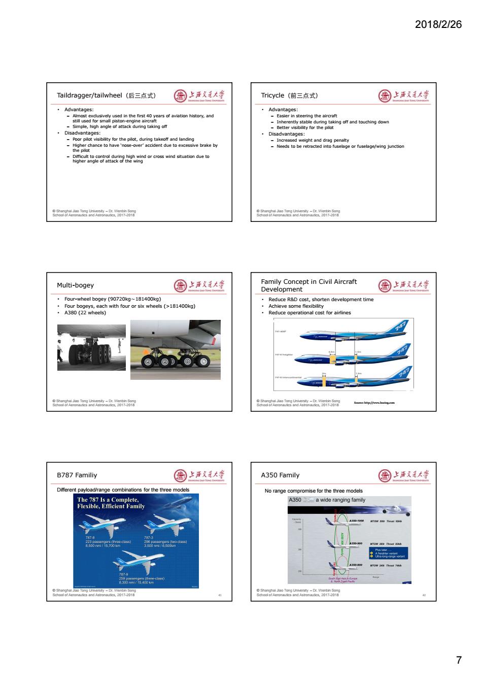
2018/2/26 7 © Shanghai Jiao Tong University – Dr. Wenbin Song School of Aeronautics and Astronautics, 2017-2018 Taildragger/tailwheel(后三点式) • Advantages: – Almost exclusively used in the first 40 years of aviation history, and still used for small piston-engine aircraft – Simple, high angle of attack during taking off • Disadvantages: – Poor pilot visibility for the pilot, during takeoff and landing – Higher chance to have ‘nose-over’ accident due to excessive brake by the pilot – Difficult to control during high wind or cross wind situation due to higher angle of attack of the wing © Shanghai Jiao Tong University – Dr. Wenbin Song School of Aeronautics and Astronautics, 2017-2018 Tricycle(前三点式) • Advantages: – Easier in steering the aircraft – Inherently stable during taking off and touching down – Better visibility for the pilot • Disadvantages: – Increased weight and drag penalty – Needs to be retracted into fuselage or fuselage/wing junction © Shanghai Jiao Tong University – Dr. Wenbin Song School of Aeronautics and Astronautics, 2017-2018 Multi-bogey • Four-wheel bogey (90720kg~181400kg) • Four bogeys, each with four or six wheels (>181400kg) • A380 (22 wheels) © Shanghai Jiao Tong University – Dr. Wenbin Song School of Aeronautics and Astronautics, 2017-2018 Family Concept in Civil Aircraft Development • Reduce R&D cost, shorten development time • Achieve some flexibility • Reduce operational cost for airlines Source: http://www.boeing.com © Shanghai Jiao Tong University – Dr. Wenbin Song School of Aeronautics and Astronautics, 2017-2018 B787 Familiy 41 Different payload/range combinations for the three models © Shanghai Jiao Tong University – Dr. Wenbin Song School of Aeronautics and Astronautics, 2017-2018 A350 Family 42 No range compromise for the three models
2018/2/26 What will next-gen narrow-body look like? 园上声克大学 国上清大学 ·When will it come? Airbus sys not until 2024,Boeing says at least 2020-why? Other planema SECTION II AIRCRAFT SYSTEMS e e o r nd 0171 Soor an0 Major Aircraft Systems 国上活美大坐 Powerplant 圆上洋廷大蜂 Power plant ·Type of powerplant Avionics and Flight Instrument -Pistol engine:small,low speed aircraft (300~400km/h) Flight Control systems -Turboprop,small regional jet (50 seats) Hydraulic system -Turbofet.military fet ·Fuel System -Turbofan,main type of engine for high speed transonic civil aircraft Wing Ramjet,hypersonic aircraft (300km/h) ·Fuselage ·Undercarriage eagaea2-w58 8oa6o0e四k-a88 Gas Turbine History at Rolls-Royce 圈上洋文大学 Avionics/Cockpit Instrument 园上海发大坐 History of the Gas Turbine at Rolls-Royce From multiple pilot crew to 2 pilot crew Increased commonality to reduce pilot training effort and cost Modern computer and electronics D: 535E4 193019401950 1960 1970 1980 1990 2000 2010 8
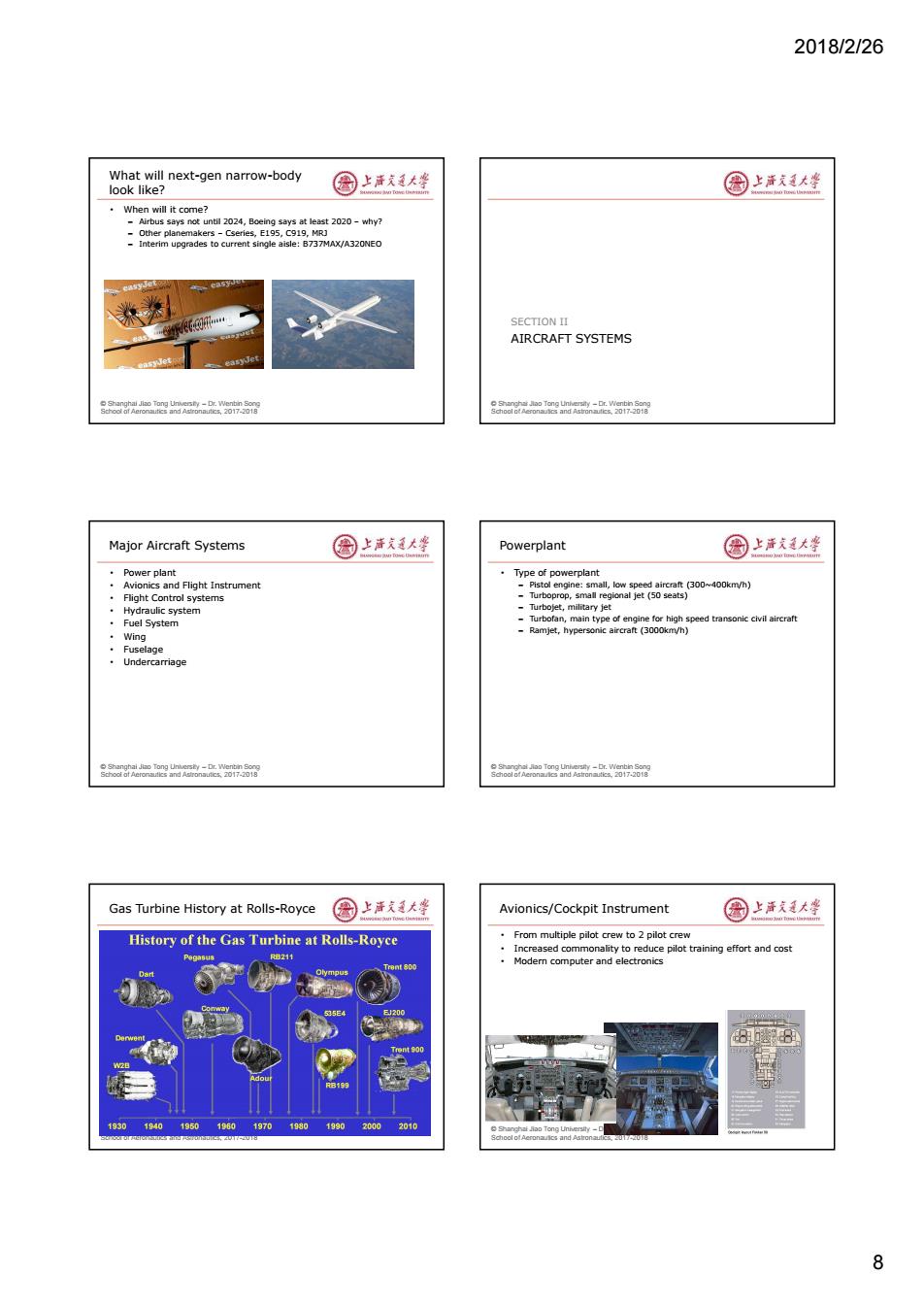
2018/2/26 8 © Shanghai Jiao Tong University – Dr. Wenbin Song School of Aeronautics and Astronautics, 2017-2018 What will next-gen narrow-body look like? • When will it come? – Airbus says not until 2024, Boeing says at least 2020 – why? – Other planemakers – Cseries, E195, C919, MRJ – Interim upgrades to current single aisle: B737MAX/A320NEO © Shanghai Jiao Tong University – Dr. Wenbin Song School of Aeronautics and Astronautics, 2017-2018 AIRCRAFT SYSTEMS SECTION II © Shanghai Jiao Tong University – Dr. Wenbin Song School of Aeronautics and Astronautics, 2017-2018 Major Aircraft Systems • Power plant • Avionics and Flight Instrument • Flight Control systems • Hydraulic system • Fuel System • Wing • Fuselage • Undercarriage © Shanghai Jiao Tong University – Dr. Wenbin Song School of Aeronautics and Astronautics, 2017-2018 Powerplant • Type of powerplant – Pistol engine: small, low speed aircraft (300~400km/h) – Turboprop, small regional jet (50 seats) – Turbojet, military jet – Turbofan, main type of engine for high speed transonic civil aircraft – Ramjet, hypersonic aircraft (3000km/h) © Shanghai Jiao Tong University – Dr. Wenbin Song School of Aeronautics and Astronautics, 2017-2018 Gas Turbine History at Rolls-Royce © Shanghai Jiao Tong University – Dr. Wenbin Song School of Aeronautics and Astronautics, 2017-2018 Avionics/Cockpit Instrument • From multiple pilot crew to 2 pilot crew • Increased commonality to reduce pilot training effort and cost • Modern computer and electronics
2018/2/26 Control and Handling 圆上活大学 Summary 国上清大学 Elevators/Ailerons/Rudder Aircraft Configuration Flaps/Slats for high lift generation Ove ·目ectrical/Hydraulic Systems Fly-by-wire systems layout :6ge Engine Installation -Undercarriage -Optical fiber(fly-by-light) ·Aircraft Systems More electric aircraft -Power plant,fuselage,wing carriage,landing gear -Power-by-wire NOT unique,and depends on factors such o r nd 0171 Soor an0 圈上活大坐 Wing Planform-sweepback angle 园上活道大整 。Rectangular■aood low.speed performance Backward Sweep-Increased critical Ma Number for transonic speed eep eve better performance for both low-speed Backup slides Mig-23 rAer 9
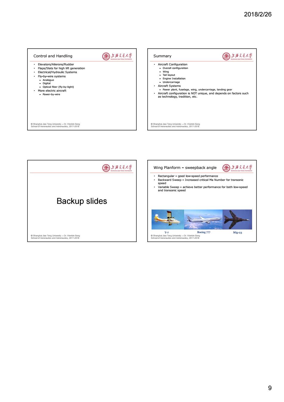
2018/2/26 9 © Shanghai Jiao Tong University – Dr. Wenbin Song School of Aeronautics and Astronautics, 2017-2018 Control and Handling • Elevators/Ailerons/Rudder • Flaps/Slats for high lift generation • Electrical/Hydraulic Systems • Fly-by-wire systems – Analogue – Digital – Optical fiber (fly-by-light) • More electric aircraft – Power-by-wire © Shanghai Jiao Tong University – Dr. Wenbin Song School of Aeronautics and Astronautics, 2017-2018 Summary • Aircraft Configuration – Overall configuration – Wing – Tail layout – Engine Installation – Undercarriage • Aircraft Systems – Power plant, fuselage, wing, undercarriage, landing gear • Aircraft configuration is NOT unique, and depends on factors such as technology, tradition, etc. © Shanghai Jiao Tong University – Dr. Wenbin Song School of Aeronautics and Astronautics, 2017-2018 Backup slides © Shanghai Jiao Tong University – Dr. Wenbin Song School of Aeronautics and Astronautics, 2017-2018 Wing Planform – sweepback angle • Rectangular – good low-speed performance • Backward Sweep – Increased critical Ma Number for transonic speed • Variable Sweep – achieve better performance for both low-speed and transonic speed Y-7 Boeing 777 Mig-23