Manufacturing Topic III Rapid prototyping
Manufacturing Topic III Rapid prototyping
Rapid Prototyping Techniques RPT allows designers to quickly generate 3D models or prototypes of parts in cheap materials. Benefits of RP: >Design improved >Potential machining problems identified
Rapid Prototyping Techniques RPT allows designers to quickly generate 3D models or prototypes of parts in cheap materials. Benefits of RP: Design improved Potential machining problems identified
>5.1 Laminated Object Manufacturing >5.2 Stereolithography >5.3 Other Rapid Modeling Techniques
5.1 Laminated Object Manufacturing 5.2 Stereolithography 5.3 Other Rapid Modeling Techniques
Laminated Object Manufacturing Creating a 3D model >Developed by Helisys in 1991 >Work 24 hours a day > Using inexpensive solid sheet material,such as ▣Paper ▣Plastic ▣Composites 口 The models (molds)can be used as direct tools for □Injection molding ▣Sand casting
Laminated Object Manufacturing Creating a 3D model Developed by Helisys in 1991 Work 24 hours a day Using inexpensive solid sheet material, such as Paper Plastic Composites … The models (molds) can be used as direct tools for Injection molding Sand casting …
The laminated object manufacturing process > Program CAD data into the LOM's X-Y positioning Laser device Layer outline process controller. and crosshatch Laser beam Generate a cross-sectional slice Laminating roller > A laser cuts the outline of the cross section and cross-hatches the excess Part block material for later removal Sheet Platform material Bond a new layer of material to the top of the previously cut layer Take-up roll The new cross section is prepared and cut Material supply roll Figure 22-17.The Laminated Object Manufacturing process
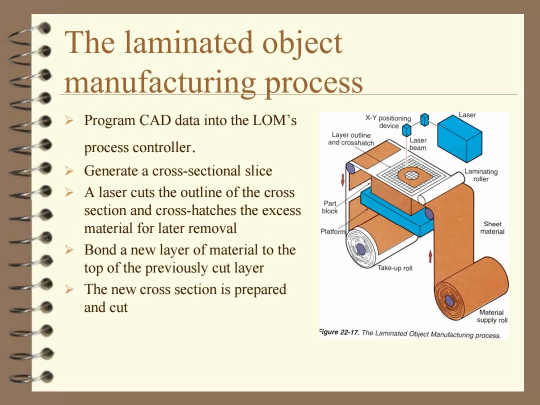
The laminated object manufacturing process Program CAD data into the LOM’s process controller. Generate a cross-sectional slice A laser cuts the outline of the cross section and cross-hatches the excess material for later removal Bond a new layer of material to the top of the previously cut layer The new cross section is prepared and cut
> The above process continues until all layers are laminated and cut > Excess material is then removed to expose the finished part >The part's surface can then be sanded,polished,or painted as desired
The above process continues until all layers are laminated and cut Excess material is then removed to expose the finished part The part’s surface can then be sanded, polished, or painted as desired
Stereolithography >Creating a 3D model >Using the liquid photocurable polymer--- can solidify when stuck(touched)by laser beam >Producing complex prototypes of castings and other objects in hours,instead of days and weeks in traditional ways
Stereolithography Creating a 3D model Using the liquid photocurable polymer--- can solidify when stuck (touched) by laser beam Producing complex prototypes of castings and other objects in hours, instead of days and weeks in traditional ways
The sterolithography process Create 3D CAD model (with a support structure) Slice the model into cross sections of 0.12mm 2.Orient and support to 0.5mm in thickness 1.CAD design 3.CAD interface Download the above CAD data into the sterolithography machine The part(model)is 10.Final cure 4.Slice created from the bottom 5.Interface up,on the platform just 9.Build 6.Merge 7.Utility below the surface of the 8.Prepare liquid photocurable polymer in a vat
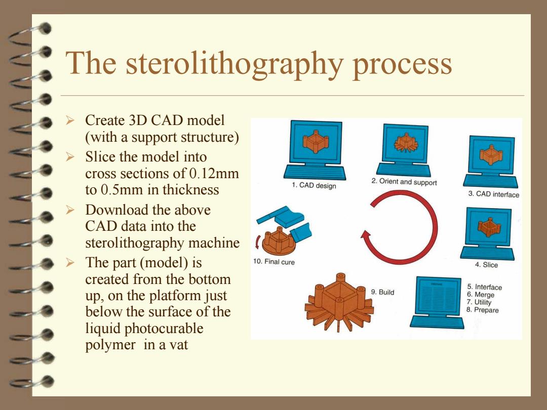
The sterolithography process Create 3D CAD model (with a support structure) Slice the model into cross sections of 0.12mm to 0.5mm in thickness Download the above CAD data into the sterolithography machine The part (model) is created from the bottom up, on the platform just below the surface of the liquid photocurable polymer in a vat
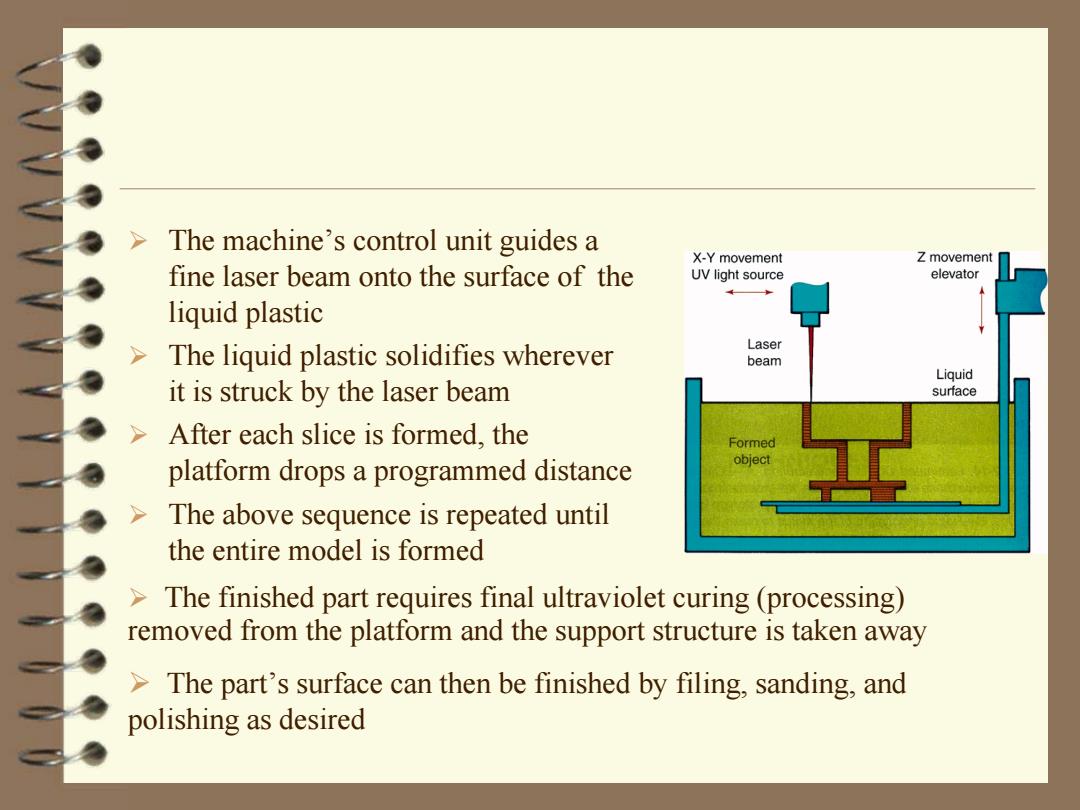
The machine's control unit guides a X-Y movement Z movement fine laser beam onto the surface of the UV light source elevator liquid plastic The liquid plastic solidifies wherever Laser beam Liquid it is struck by the laser beam surface After each slice is formed,the Formed platform drops a programmed distance object The above sequence is repeated until the entire model is formed The finished part requires final ultraviolet curing (processing) removed from the platform and the support structure is taken away >The part's surface can then be finished by filing,sanding,and polishing as desired
The machine’s control unit guides a fine laser beam onto the surface of the liquid plastic The liquid plastic solidifies wherever it is struck by the laser beam After each slice is formed, the platform drops a programmed distance The above sequence is repeated until the entire model is formed The finished part requires final ultraviolet curing (processing) removed from the platform and the support structure is taken away The part’s surface can then be finished by filing, sanding, and polishing as desired
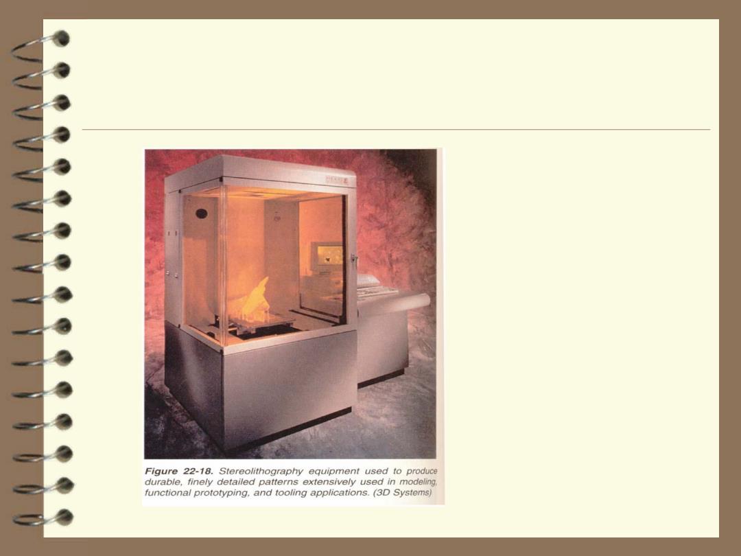
888444444441n Figure 22-18.Stereolithography equipment used to produce durable,finely detailed patterns extensively used in modeling functional prototyping.and tooling applications.(3D Systems)