A comparative study of concrete filled composite columns and steel reinforced concrete columns Girolomini Mattia Composite Structures Report
A comparative study of concrete filled composite columns and steel reinforced concrete columns Girolomini Mattia Composite Structures Report
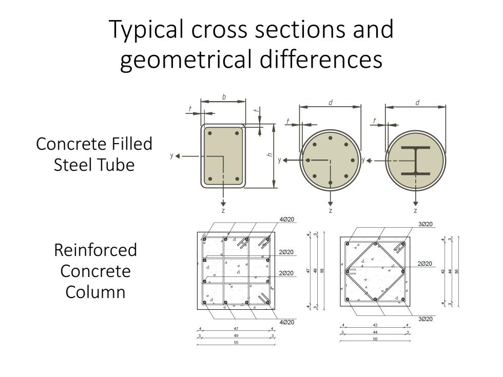
Typical cross sections and geometrical differences Concrete Filled Steel Tube 4020 3020 Reinforced 2020 2020 Concrete 2020 Column 4020 3020 42
Typical cross sections and geometrical differences Concrete Filled Steel Tube Reinforced Concrete Column
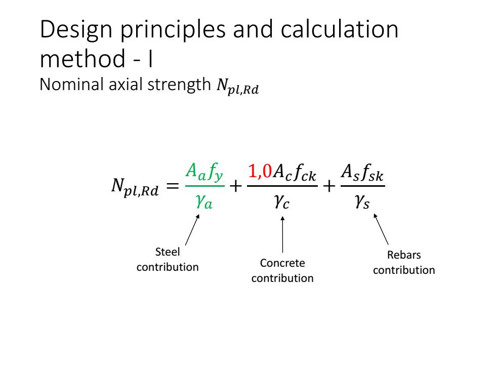
Design principles and calculation method 1 Nominal axial strength NpLRa Npl,Rd= Aafy 1,0AcfckAsfsk 十 Ya Yc Ys Steel Rebars contribution Concrete contribution contribution
Design principles and calculation method - I Nominal axial strength 𝑁𝑝𝑙,𝑅𝑑 𝑁𝑝𝑙,𝑅𝑑 = 𝐴𝑎𝑓𝑦 𝛾𝑎 + 1,0𝐴𝑐𝑓𝑐𝑘 𝛾𝑐 + 𝐴𝑠𝑓𝑠𝑘 𝛾𝑠 Steel contribution Concrete contribution Rebars contribution
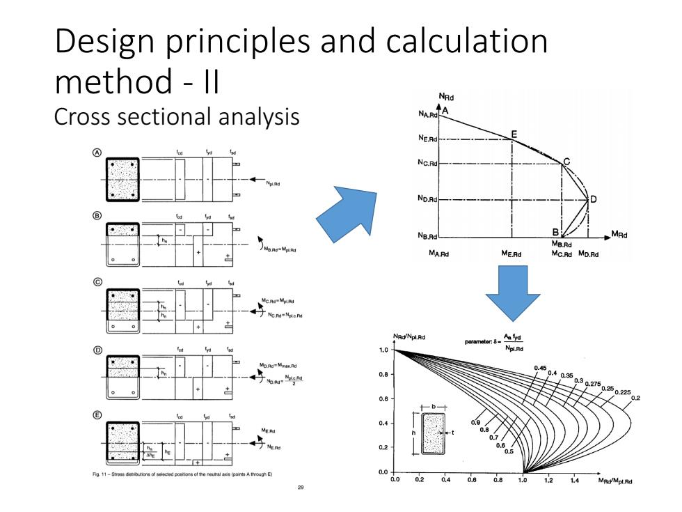
Design principles and calculation method Il Cross sectional analysis NC.R ⑧ NB.Rd B MRd MB Rd MA.Rd ME.Rd Mc附M.Ad 0.0 02 12 1.4 MRa/Mpl.Rd
Design principles and calculation method - II Cross sectional analysis

Design principles and calculation method I1I Concrete confinement In CFSTs In RCCs The ductility of the CFST is enhanced
Design principles and calculation method - III Concrete confinement In CFSTs In RCCs The ductility of the CFST is enhanced
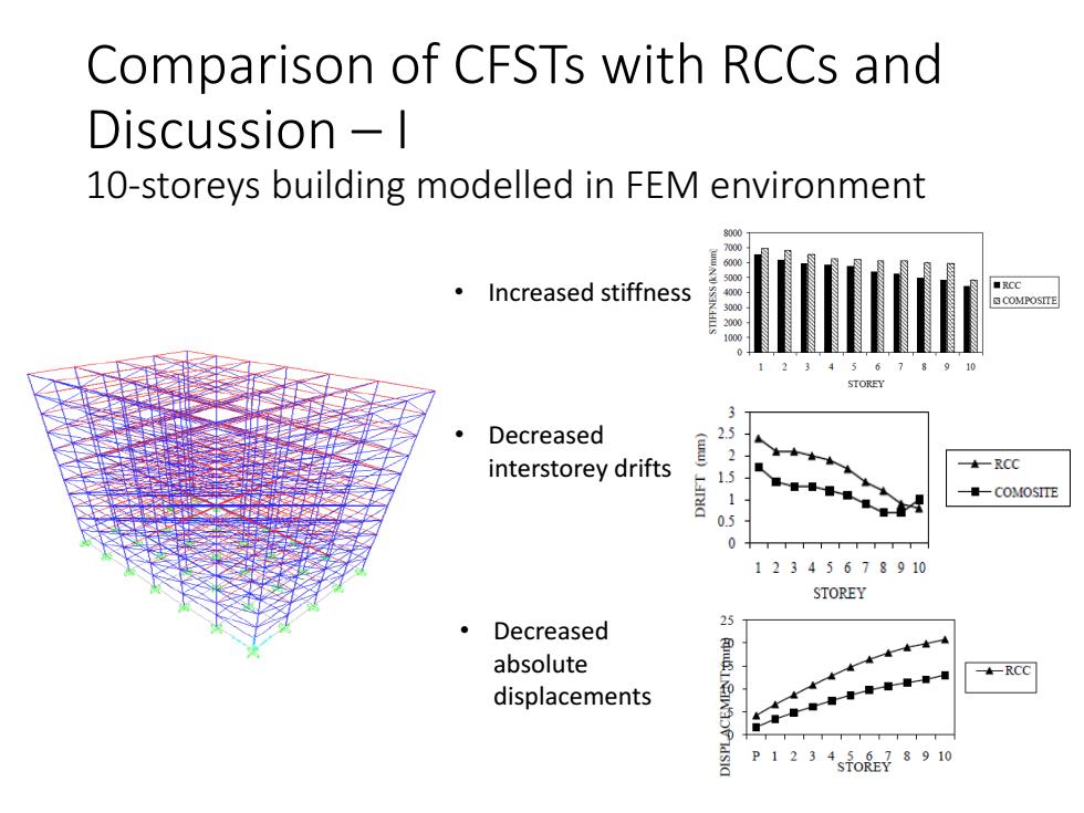
Comparison of CFSTs with RCCs and Discussion -I 10-storeys building modelled in FEM environment 8000 ·Increased stiffness ■RCC 45 STORE Decreased 23 2 interstorey drifts ★—RCC COMOSITE 12345678910 STOREY Decreased 25 absolute displacements anspeimvaoe RCC P1234sio原78910
Comparison of CFSTs with RCCs and Discussion – I 10-storeys building modelled in FEM environment • Increased stiffness • Decreased interstorey drifts • Decreased absolute displacements

Comparison of CFSTs with RCCs and Discussion -ll 10-storeys building modelled in FEM environment 140 器 ·Decreased ■RCG shear stress C1C2C3C6C7C8C1C1116118 COLUMN Decreased 念 ■RCC bending moment COLUMN 8000 Decreased axial ■RCC force C1C2C3C6C7C8C1C1116118 cOLUMN
Comparison of CFSTs with RCCs and Discussion – II 10-storeys building modelled in FEM environment • Decreased shear stress • Decreased bending moment • Decreased axial force
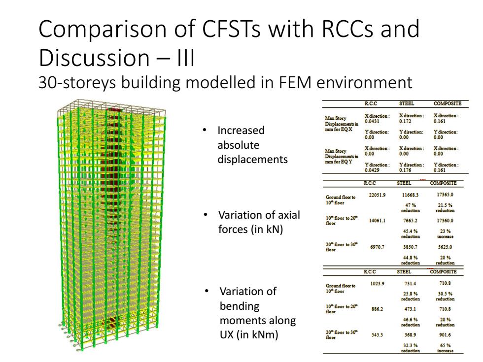
Comparison of CFSTs with RCCs and Discussion lll 30-storeys building modelled in FEM environment RCC STEEL COMPOSITE oa:8rtoa:nioa Increased oEX gtcen: oe甜rtom absolute Max Story 8新tio: ci displacements RC.C STEEL COMPOSITE famw 22051.9 11668.3 17365.0 5% Variation of axial lgaorw20 14061.1 76652 17360.0 forces (in kN) i80aoro30 6970.7 3850.1 5625.0 s 。 RC.C STEEL COMPOSITE】 Variation of f89ndaern 1023.9 731.4 710.3 8 bending cnorw20 8862 473.1 710.8 moments along 46.6% reduction UX (in kNm) 2gaoro3r 5453 363.9 901.6 33%
Comparison of CFSTs with RCCs and Discussion – III 30-storeys building modelled in FEM environment • Increased absolute displacements • Variation of axial forces (in kN) • Variation of bending moments along UX (in kNm)

Comparison of CFSTs with RCCs and Discussion -IV 15-storeys building modelled in FEM environment Column axial Forces Decreased axial forces 票CCruc间 2h3rd711h15h Nodal Displacement(mm) Increased absolute -CCU.em displacement 11h15 1230000 Cost of Columns ·Reduction of the construction 0015 costs
Comparison of CFSTs with RCCs and Discussion – IV 15-storeys building modelled in FEM environment • Decreased axial forces • Increased absolute displacement • Reduction of the construction costs