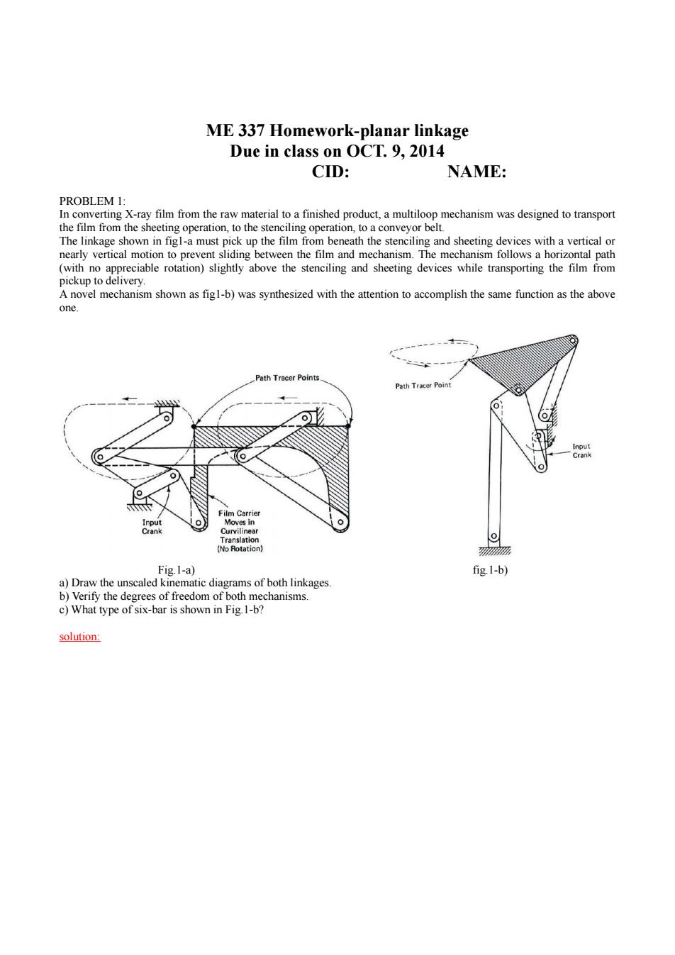
ME 337 Homework-planar linkage Due in class on OCT.9,2014 CID: NAME: PROBLEM 1: In converting X-ray film from the raw material to a finished product,a multiloop mechanism was designed to transport the film from the sheeting operation,to the stenciling operation,to a conveyor belt. The linkage shown in figl-a must pick up the film from beneath the stenciling and sheeting devices with a vertical or nearly vertical motion to prevent sliding between the film and mechanism.The mechanism follows a horizontal path (with no appreciable rotation)slightly above the stenciling and sheeting devices while transporting the film from pickup to delivery. A novel mechanism shown as figl-b)was synthesized with the attention to accomplish the same function as the above one. Path Tracer Points. Path Tracer Point Input Crank Film Carrier Input Moves in Crank Curvilinear Translation (No Rotation) 汤 Fig.1-a) fig.1-b) a)Draw the unscaled kinematic diagrams of both linkages. b)Verify the degrees of freedom of both mechanisms. c)What type of six-bar is shown in Fig.1-b? solution:
ME 337 Homework-planar linkage Due in class on OCT. 9, 2014 CID: NAME: PROBLEM 1: In converting X-ray film from the raw material to a finished product, a multiloop mechanism was designed to transport the film from the sheeting operation, to the stenciling operation, to a conveyor belt. The linkage shown in fig1-a must pick up the film from beneath the stenciling and sheeting devices with a vertical or nearly vertical motion to prevent sliding between the film and mechanism. The mechanism follows a horizontal path (with no appreciable rotation) slightly above the stenciling and sheeting devices while transporting the film from pickup to delivery. A novel mechanism shown as fig1-b) was synthesized with the attention to accomplish the same function as the above one. Fig.1-a) fig.1-b) a) Draw the unscaled kinematic diagrams of both linkages. b) Verify the degrees of freedom of both mechanisms. c) What type of six-bar is shown in Fig.1-b? solution:

.13 The kinematic P 5 diagram of D the linkage shown in F9.P1-4 The kinematic diagram of the linkage shown in Fig.P1-13 b)Stephenson m PROBLEM 2: Determine the transmission and deviation angles for the following mechanisms,for the case where a)link 2 is the input and link 6 is the output. b)link 6 is the input and link 2 is the output Solution:
PROBLEM 2: Determine the transmission and deviation angles for the following mechanisms, for the case where a) link 2 is the input and link 6 is the output. b) link 6 is the input and link 2 is the output Solution:

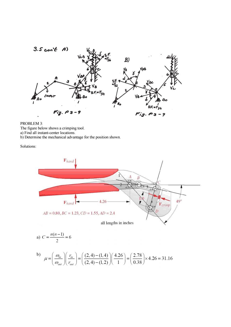
3.5 con't A) 5=F54 F的、P3-9 Fi9.°3-9 PROBLEM 3: The figure below shows a crimping tool. a)Find all instant-center locations b)Determine the mechanical advantage for the position shown. Solutions: Fhand B Fhand 4.26 499 c汽iwp 4B=0.80.BC=1.23.CD=1.55.AD=2.4 all lengths in inches a)C-M(n-D=6 2 b) In - 0.38 ×4.26=31.16
PROBLEM 3: The figure below shows a crimping tool. a) Find all instant-center locations. b) Determine the mechanical advantage for the position shown. Solutions:

PROBLEM 4: Find all the instant centers of the linkages shown in the following figures. 3 A (D2 2 02 23) B 2 4 2 0 Assume rolling contact (a) (b) C 3 B 02 002 2 13红一 Assume rolling contact Assume rolling contact (c) (d) (2.4@ 002 B 0% 3 03 Assume roll-slide contact 1 (12) (e) (f)
PROBLEM 4: Find all the instant centers of the linkages shown in the following figures