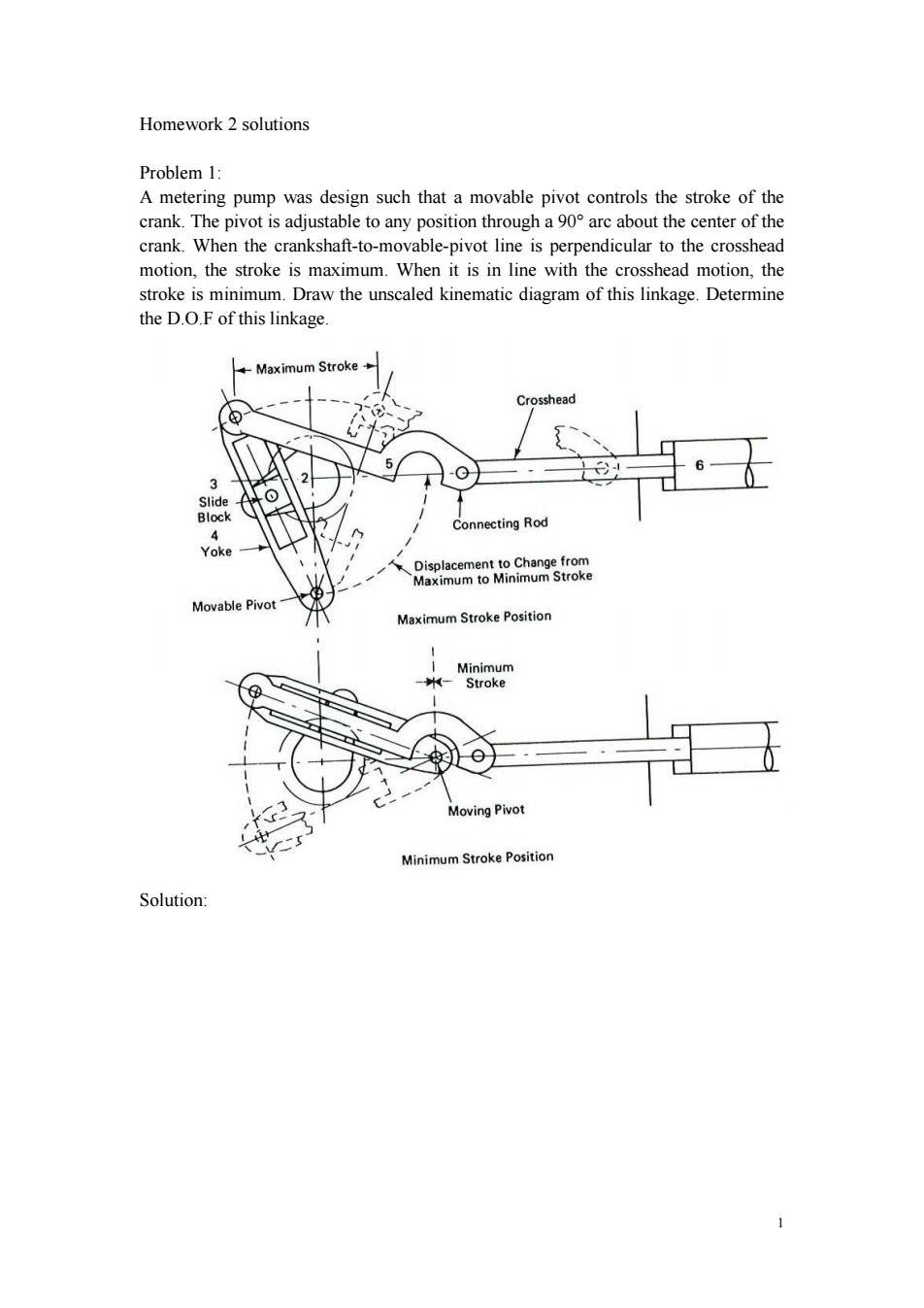
Homework 2 solutions Problem 1: A metering pump was design such that a movable pivot controls the stroke of the crank.The pivot is adjustable to any position through a 90 arc about the center of the crank.When the crankshaft-to-movable-pivot line is perpendicular to the crosshead motion,the stroke is maximum.When it is in line with the crosshead motion,the stroke is minimum.Draw the unscaled kinematic diagram of this linkage.Determine the D.O.F of this linkage. -Maximum Stroke Crosshead 3 Slide Block Connecting Rod 4 Yoke Displacement to Change from Maximum to Minimum Stroke Movable Pivot Maximum Stroke Position Minimum -Stroke Moving Pivot Minimum Stroke Position Solution:
1 Homework 2 solutions Problem 1: A metering pump was design such that a movable pivot controls the stroke of the crank. The pivot is adjustable to any position through a 90° arc about the center of the crank. When the crankshaft-to-movable-pivot line is perpendicular to the crosshead motion, the stroke is maximum. When it is in line with the crosshead motion, the stroke is minimum. Draw the unscaled kinematic diagram of this linkage. Determine the D.O.F of this linkage. Solution:
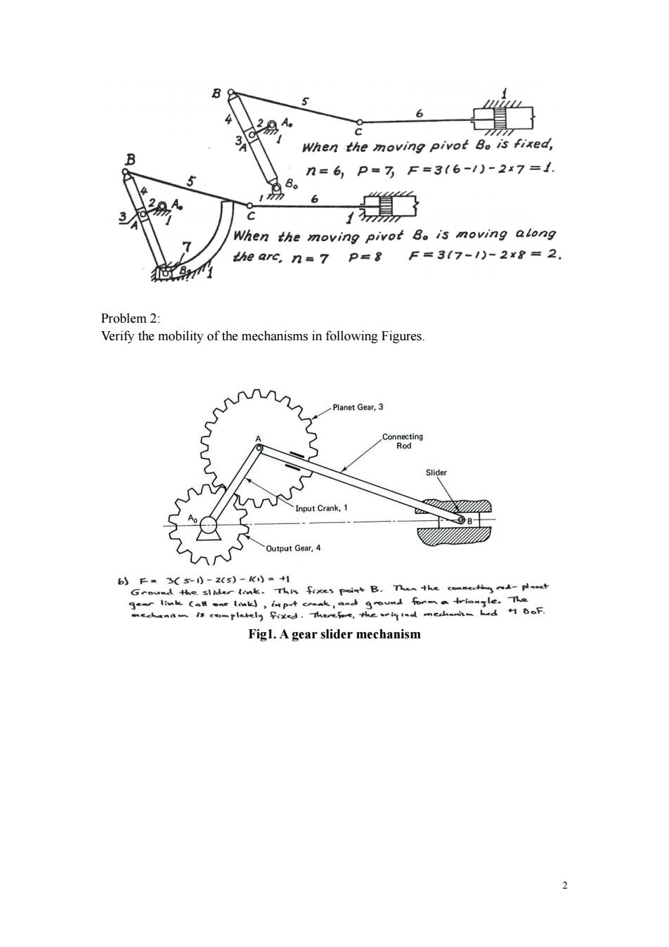
B 2易 ● 6 When the moving pivot Bo is fixed, B n=6,P=7F=3(6-1)-2x7=1. 5 6 3 C When the moving pivot Bo is moving along the arc,n=7 P=8 F=317-1)-2×8=2 Problem 2: Verify the mobility of the mechanisms in following Figures. ununhnn Planet Gear,3 Connecting Rod Slider Input Crank,1 、wi2 ©B Output Gear,4 6)F3(50-2(5)-)=+1 Gro心dhes到d《mk。This fixe3peiB.Then the conner与~d-pt ge link (al sne lmk)inpt coank,and ground forma triangle.The meckann一作co一rll与子ed.ee,h作dme山一d10oF Fig1.A gear slider mechanism 2
2 Problem 2: Verify the mobility of the mechanisms in following Figures. Fig1. A gear slider mechanism
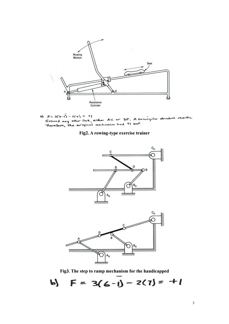
Seat 9 0 Resistance Cylinder bF.3(y-5-2(4\-+1 Ground any ofter link,eite A-c r DF.A tnienul ucht rewis. tee,tHeo妈inal mechan的n人.+1 DoF Fig2.A rowing-type exercise trainer Co Co D ● 60 Fig3.The step to ramp mechanism for the handicapped )F=3(6-)-2(7)=+1 3
3 Fig2. A rowing-type exercise trainer Fig3. The step to ramp mechanism for the handicapped
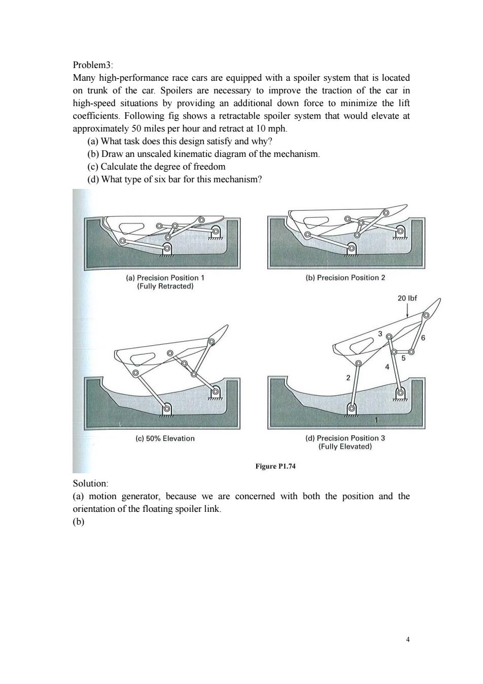
Problem3: Many high-performance race cars are equipped with a spoiler system that is located on trunk of the car.Spoilers are necessary to improve the traction of the car in high-speed situations by providing an additional down force to minimize the lift coefficients.Following fig shows a retractable spoiler system that would elevate at approximately 50 miles per hour and retract at 10 mph (a)What task does this design satisfy and why? (b)Draw an unscaled kinematic diagram of the mechanism. (c)Calculate the degree of freedom (d)What type of six bar for this mechanism? (a)Precision Position 1 (b)Precision Position 2 (Fully Retracted) 20 Ibf 5 》 n办 (c)50%Elevation (d)Precision Position 3 (Fully Elevated) Figure P1.74 Solution: (a)motion generator,because we are concerned with both the position and the orientation of the floating spoiler link. (b) 4
4 Problem3: Many high-performance race cars are equipped with a spoiler system that is located on trunk of the car. Spoilers are necessary to improve the traction of the car in high-speed situations by providing an additional down force to minimize the lift coefficients. Following fig shows a retractable spoiler system that would elevate at approximately 50 miles per hour and retract at 10 mph. (a) What task does this design satisfy and why? (b) Draw an unscaled kinematic diagram of the mechanism. (c) Calculate the degree of freedom (d) What type of six bar for this mechanism? Solution: (a) motion generator, because we are concerned with both the position and the orientation of the floating spoiler link. (b)
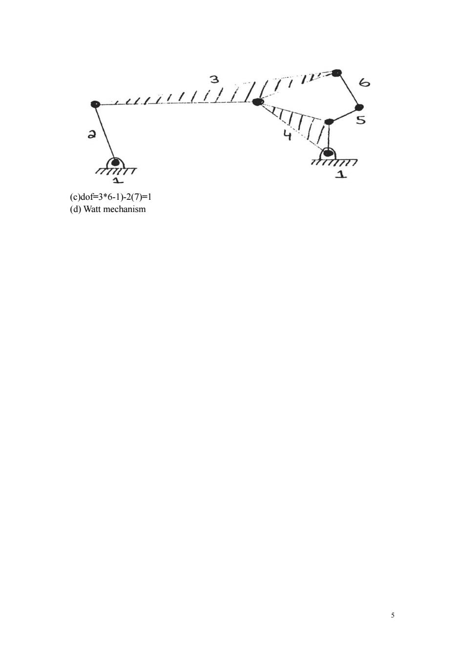
S a 777/77 1 (c)dof3*6-1)2(7)=1 (d)Watt mechanism 5
5 (c)dof=3*6-1)-2(7)=1 (d) Watt mechanism