Chapter 5 Transform Analysis of Linear Time-Invariant Systems ◆5.0 Introduction 5.1 Frequency Response of LTI Systems 5.2 System Functions For Systems Characterized by Linear Constant-coefficient Difference equation 5.3 Frequency Response for Rational System Functions 5.4 Relationship Between Magnitude and Phase ◆5.5All-Pass System 5.6 Minimum-Phase Systems 5.7 Linear Systems with Generalized Linear Phase 2
Chapter 5 Transform Analysis of Linear Time-Invariant Systems ◆5.0 Introduction ◆5.1 Frequency Response of LTI Systems ◆5.2 System Functions For Systems Characterized by Linear Constant-coefficient Difference equation ◆5.3 Frequency Response for Rational System Functions ◆5.4 Relationship Between Magnitude and Phase ◆5.5 All-Pass System ◆5.6 Minimum-Phase Systems ◆5.7 Linear Systems with Generalized Linear Phase 2
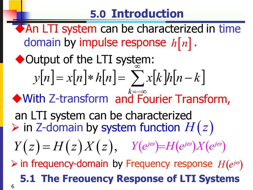
5.0 Introduction An LTI system can be characterized in time domain by impulse response[]. Output of the LTI system: yIn]=xIn]*hin]=>xkhin-k] With Z-transform and Fourier Transform, an LTI system can be characterized >in Z-domain by system function H(z) Y(z)=H(z)X(z),Y(e)=H()x(e) in frequency-domain by Frequency response H(e) 5.1 The Freouency Response of LTI Systems 6
5.0 Introduction ◆An LTI system can be characterized in time domain by impulse response . ◆Output of the LTI system: h n =− = = − k y n x n h n x k h n k Y z H z X z ( ) = ( ) ( ), ➢ in Z-domain by system function ➢ in frequency-domain by Frequency response ( ) ( ) ( ) j j j Y e H e X e = ◆With Z-transform an LTI system can be characterized H z( ) ( ) H ej and Fourier Transform, 6 5.1 The Freouency Response of LTI Systems

5.1.1 Frequency Response Phase and Group Delay The phase angle of any complex number is not uniquely defined,since 2nr can be added without affecting the complex number. H@)HH(eYeKMoy2nrHF1(@wY-Hm) ◆denote Principal Value(主值)of the phase of H(eo) -π<ARG[H(eo]≤π ambiguous phase不确定的相位 arbitrary ∠H(eo)=ARG[H(e]+2rr(o where r(@)is a positive or negative integer that can be different at each value of o. 11
5.1.1 Frequency Response Phase and Group Delay ◆The phase angle of any complex number is not uniquely defined, since 2πr can be added without affecting the complex number. ( ) ( ) 2 ( ) H ej H j ARG e r = + ( ) H ej ARG − ◆denote Principal Value(主值) of the phase of ( ) H ej ambiguous phase 11 where is a positive or negative integer r() 不确定的相位 ( ) ( ) ( ( ) 2 ) j j j j H e r H e H e e + = ( ) j ( ) j j H e H e e = arbitrary that can be different at each value of
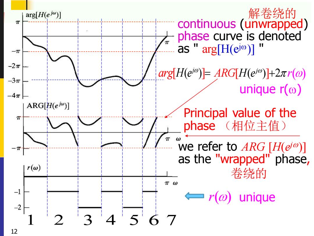
arg[H(e)] 解卷绕的 入 continuous (unwrapped) phase curve is denoted 一7T as "arg[H(el)] -2π arg H(e)=ARGH(e)+2r(@ -3T -4π unique r() ARG[H(e)] n Principal value of the phase(相位主值) we refer to ARG [H(ei)] as the e "wrapped"phase r(@) 卷绕的 TW ←一r(o) unique 3'4 12
1 2 3 4 5 6 7[ ( ) ] j arg H e = we refer to ARG [ H( ej )] as the "wrapped" phase , continuous (unwrapped) phase curve is denoted as " arg[H(ej )] " 卷绕的 解卷绕的 [ ( ) ] 2 ( ) H ej ARG r + Principal value of the phase (相位主值) 12 r () unique r( ) unique
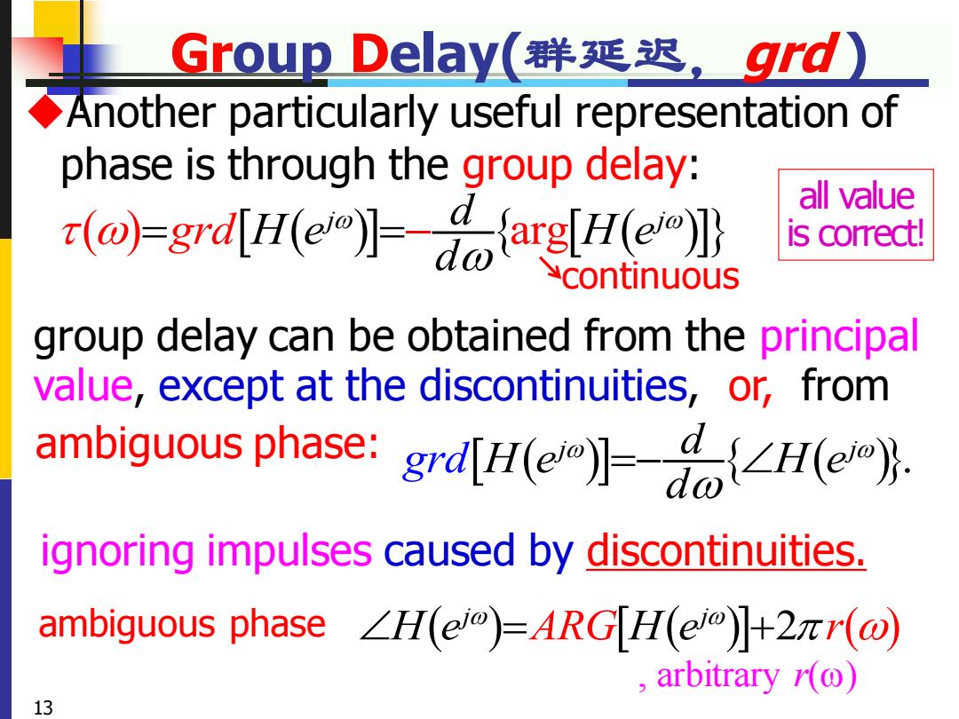
Group delay( 群延迟,gd) Another particularly useful representation of phase is through the group delay: all value ()-grdu is correct! continuous group delay can be obtained from the principal value,except at the discontinuities,or,from ambiguous phase:grd[H(e】=a{∠Hleo} ignoring impulses caused by discontinuities. ambiguous phase∠H(em)=ARGH(em】+2rr(o) ,arbitrary(o) 13
Group Delay(群延迟,grd ) ( ) ( ) arg ( ) j j d grd H e H e d = =− group delay can be obtained from the principal value, except at the discontinuities, ◆Another particularly useful representation of phase is through the group delay: ( ) ( ) 2 ( ) H e H j j ARG r e = + continuous ambiguous phase , arbitrary r() 13 ( ) ( ). j j d g d H e H e d r =− ignoring impulses caused by discontinuities. or, from ambiguous phase: all value is correct!
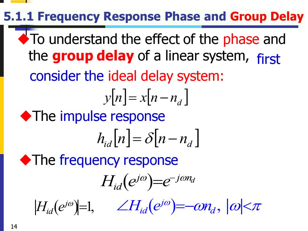
5.1.1 Frequency Response Phase and Group Delay To understand the effect of the phase and the group delay of a linear system,first consider the ideal delay system: yn =xn-na. ◆The impulse response haln]=n-na The frequency response Hid(ej)-e jon H(el,∠Hna(eo)=-u,ll水k元 14
5.1.1 Frequency Response Phase and Group Delay hid n = n − nd n nd y n = x − ( ) d j j n H e e id − = ( ) 1, j H e id = ( ) , j H e n id d =− ◆The frequency response ◆The impulse response ◆To understand the effect of the phase and the group delay of a linear system, first consider the ideal delay system: 14
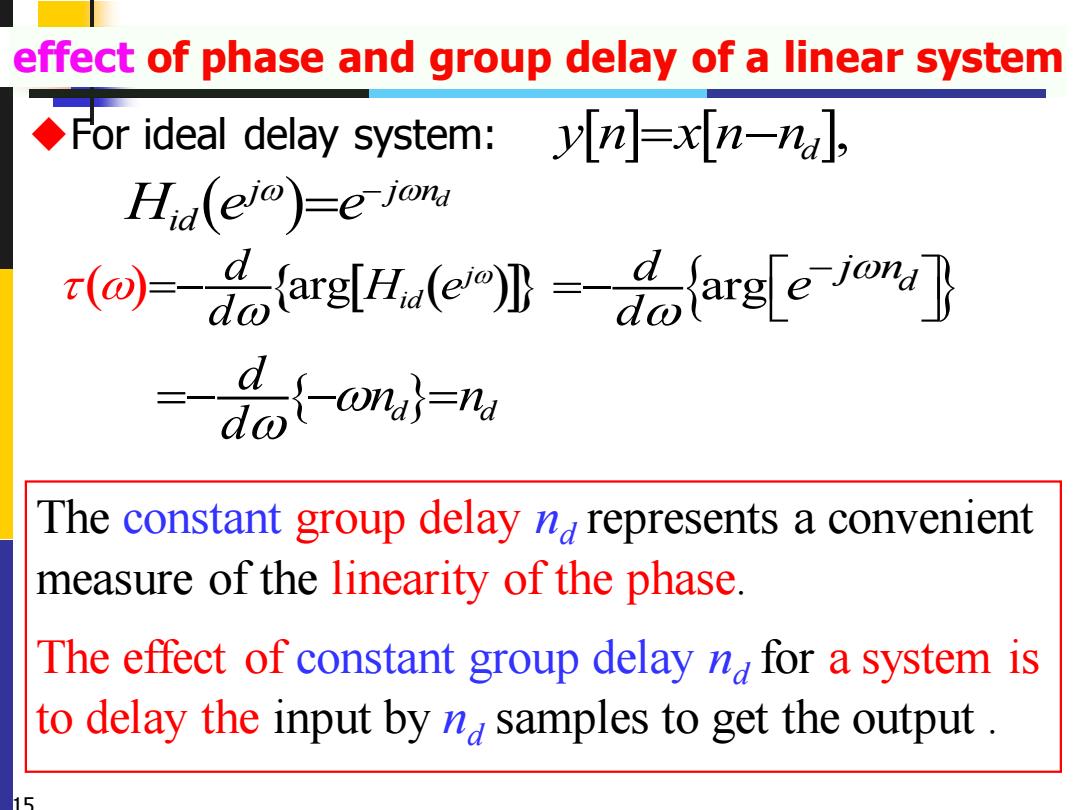
effect of phase and group delay of a linear system For ideal delay system:n Hid(eio)e-jon r(a)-farg(arge or =%{-om}, The constant group delay nrepresents a convenient measure of the linearity of the phase. The effect of constant group delay na for a system is to delay the input by n samples to get the output
effect of phase and group delay of a linear system ◆For ideal delay system: d d d n n d =− − = The constant group delay nd represents a convenient measure of the linearity of the phase. The effect of constant group delay nd for a system is to delay the input by nd samples to get the output . ( ) arg ( ) j id d H e d =−( ) d j j n H e e id − = , y n x n n = − d 15 arg d d j n d e − =− The constant group delay represents a convenient
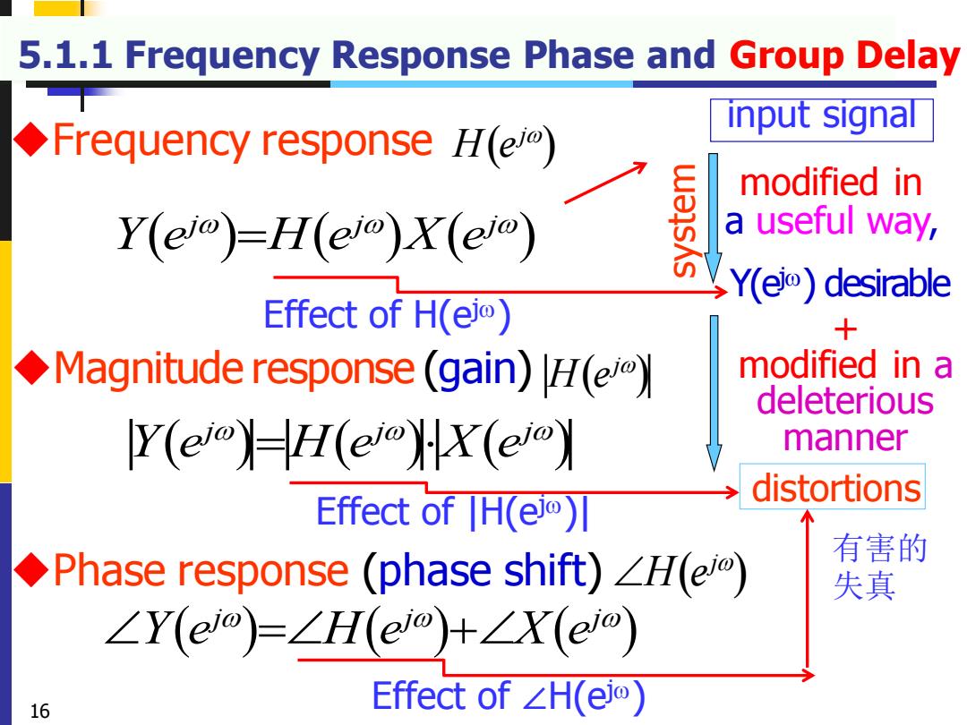
5.1.1 Frequency Response Phase and Group Delay input signal Frequency response H(el) modified in Y(eo)=lH(eo)X(em) a useful way, Ye)desirable Effect of H(ei) 十 Magnitude response (gain)H(ei) modified in a deleterious Y(ei-H(ei)X(e) manner distortions Effect of |H(eo刃 ◆Phase response(phase shift)∠H(eo) 有害的 失真 ∠Y(eo)=∠H(eo+∠X(eo) 16 Effect of∠H(eio)
5.1.1 Frequency Response Phase and Group Delay ( ) ( ) ( ) j j j Y e H e X e = ( ) ( ) ( ) j j j Y e H e X e = ◆Phase response (phase shift) ( ) H ej ( ) ( ) ( ) j j j Y e H e X e = + ( ) ◆ H ej Frequency response ( ) ◆Magnitude response H ej (gain) distortions modified in a useful way, system input signal 16 Y(e j) desirable + modified in a deleterious manner Effect of H(ej) Effect of |H(ej)| Effect of ∠H(ej) 有害的 失真
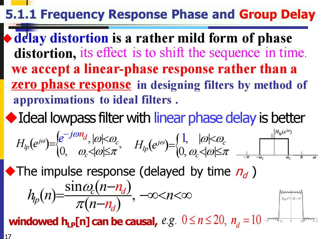
5.1.1 Frequency Response Phase and Group Delay delay distortion is a rather mild form of phase distortion,its effect is to shift the sequence in time. we accept a linear-phase response rather than a zero phase response in designing filters by method of approximations to ideal filters Ideal lowpass filter with linear phase delay is better ue-本2e四设apgn Hp(e) The impulse response(delayed by time nd) (sing( 元(n-nu -00<1n<00 Ht四相=9 windowed hpl[n]can be causal,,e.g.0≤n≤20,n=l0 17
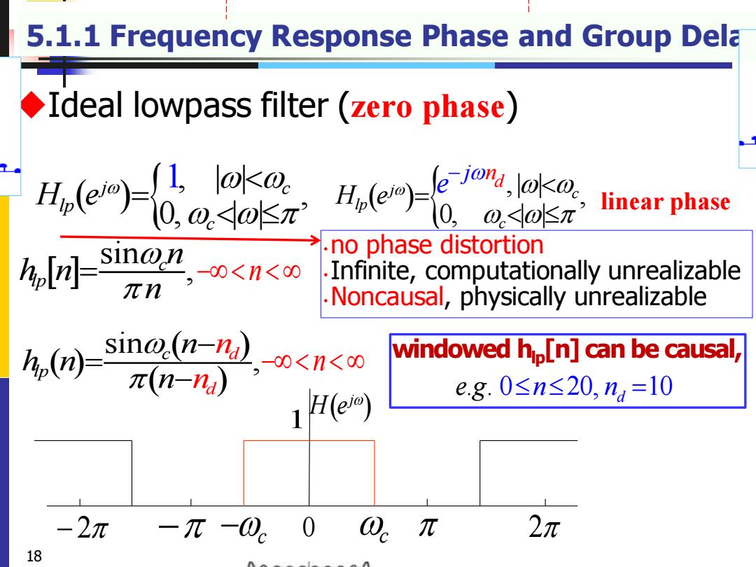
5.1.1 Frequency Response Phase and Group Delay ◆Ideal lowpass filter with linear phase delay is better ( ) ,| | , 0, | | j c lp c d j n H e e − = ◆delay distortion is a rather mild form of phase distortion, ◆The impulse response (delayed by time nd ) its effect is to shift the sequence in time. 17 in designing filters by method of approximations to ideal filters . windowed hLP[n] can be causal, ( ) ( ) ( ) sin , c d lp d n h n n n n n − = − − we accept a linear-phase response rather than a zero phase response . . 0 20, 10 d e g = n n ( ) , | | 0, | | j 1 c lp c H e =
5.1.1 Frequency Response Phase and Group Dela Ideal lowpass filter (zero phase) e-ae生 e8 0,o4o昨元 linear phase a,-s1ng”,o<n< no phase distortion Infinite,computationally unrealizable 元n Noncausal,physically unrealizable sin@(n-na)oo<n<c windowed hp[n]can be causal, π(n-na) 1H(e) e.g.0≤n≤20,n=l0 -2π 0 π 2元 18
5.1.1 Frequency Response Phase and Group Delay ◆Ideal lowpass filter (zero phase) ( ) j H e − 2 − −c 0 c 2 1 sin , c lp n h n n = 18 − n k y n x k h n k =− = − windowed hlp[n] can be causal, . . 0 20, 10 d e g = n n •no phase distortion •Infinite, computationally unrealizable •Noncausal, physically unrealizable ( ) ,| | , 0, | | j c lp c d j n H e e − = ( ) ( ) ( ) sin , d d c lp n h n n n n − = − ( ) , | | , 0, | | j 1 c lp c H e = − n linear phase