Heat Pumping Processes and Systems Introduction to Thermodynamic analysis Monday June 30th 2014 Trygve M.Eikevik Professor Norwegian University of Science and Technology(NTNU) E-mail;trygve.m.eikevik@ntnu.no http://folk.ntnu.no/tme 职 ONTNU ②SINTEF shrae 2010 ASHRAE HANDE①底 http://www.ashrae.com REFRIGERATION E服证 3pps6i防A8AgR8aaeh 回NTNU SINTEF
1 Heat Pumping Processes and Systems Introduction to Thermodynamic analysis Monday June 30th 2014 Trygve M. Eikevik Professor Norwegian University of Science and Technology (NTNU) E-mail; trygve.m.eikevik@ntnu.no http://folk.ntnu.no/tme 2 http://www.ashrae.com/ http://www.ashrae.com
Usefull links ·http:lw.ifir.org International Institute of Refrigeration 。http:lw.iar.org International Institute of Ammonia Refrigeration ·http:lw.R744.com WEB page for Natural Refrigerant R744(CO2) ·htp:/w.R717.com WEB page for the Ammonia systems Useful programs from DTU;CoolPack,SecCool,Pack Calculation Il.Simple one-stage CO2 http://www.ipu.dk/English/IPU-Manufacturing/Refrigeration-and-energy-technology/Downloads/CoolPack.aspx ONTNU ②SINTEF Refrigeration system Heat flow,Q. 级深88避宽 out Soa water Receiver ③ Condensor(Pe,t) Electricity, W Compressor evaporator(po,to) motor in air ◆Out Expansion valve Heat flow,Q。 ONTNU SINTEF
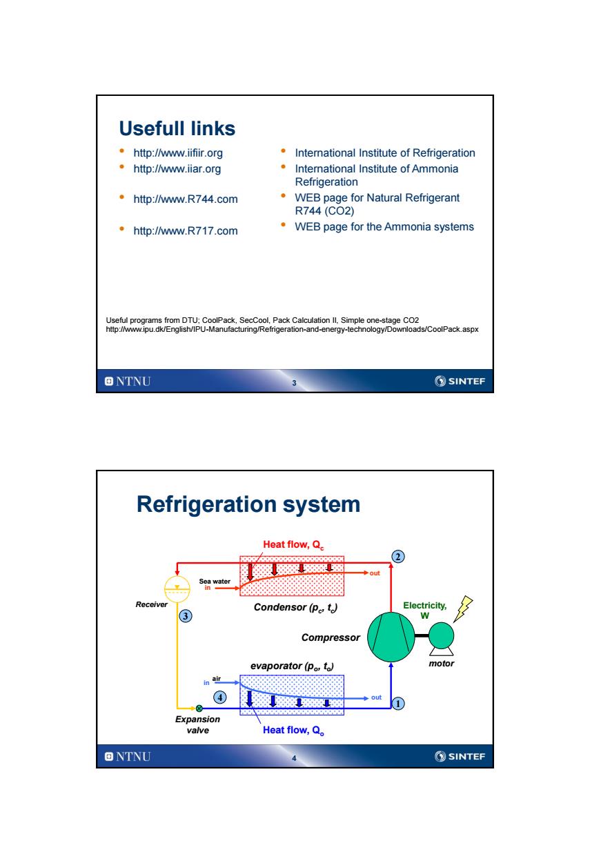
3 Usefull links • http://www.iifiir.org • http://www.iiar.org • http://www.R744.com • http://www.R717.com • International Institute of Refrigeration • International Institute of Ammonia Refrigeration • WEB page for Natural Refrigerant R744 (CO2) • WEB page for the Ammonia systems Useful programs from DTU; CoolPack, SecCool, Pack Calculation II, Simple one-stage CO2 http://www.ipu.dk/English/IPU-Manufacturing/Refrigeration-and-energy-technology/Downloads/CoolPack.aspx 4 air in evaporator (po , to ) Condensor (pc , tc ) in out Sea water Heat flow, Qc Heat flow, Qo Compressor Expansion valve Receiver motor Electricity, W Refrigeration system out 1 4 3 2
Operation based on two important effects 1.The Pressure of the working fluid within the vapor/liquid (two phase)area is decided by the Temperature only. 2.Liquid that evaporates,takes up(absorb)heat, while vapor that condenses,release heat ONTNU ②SINTEF Propane(R290) Gas phase 医 Liquid phase ▣NTNU SINTEF
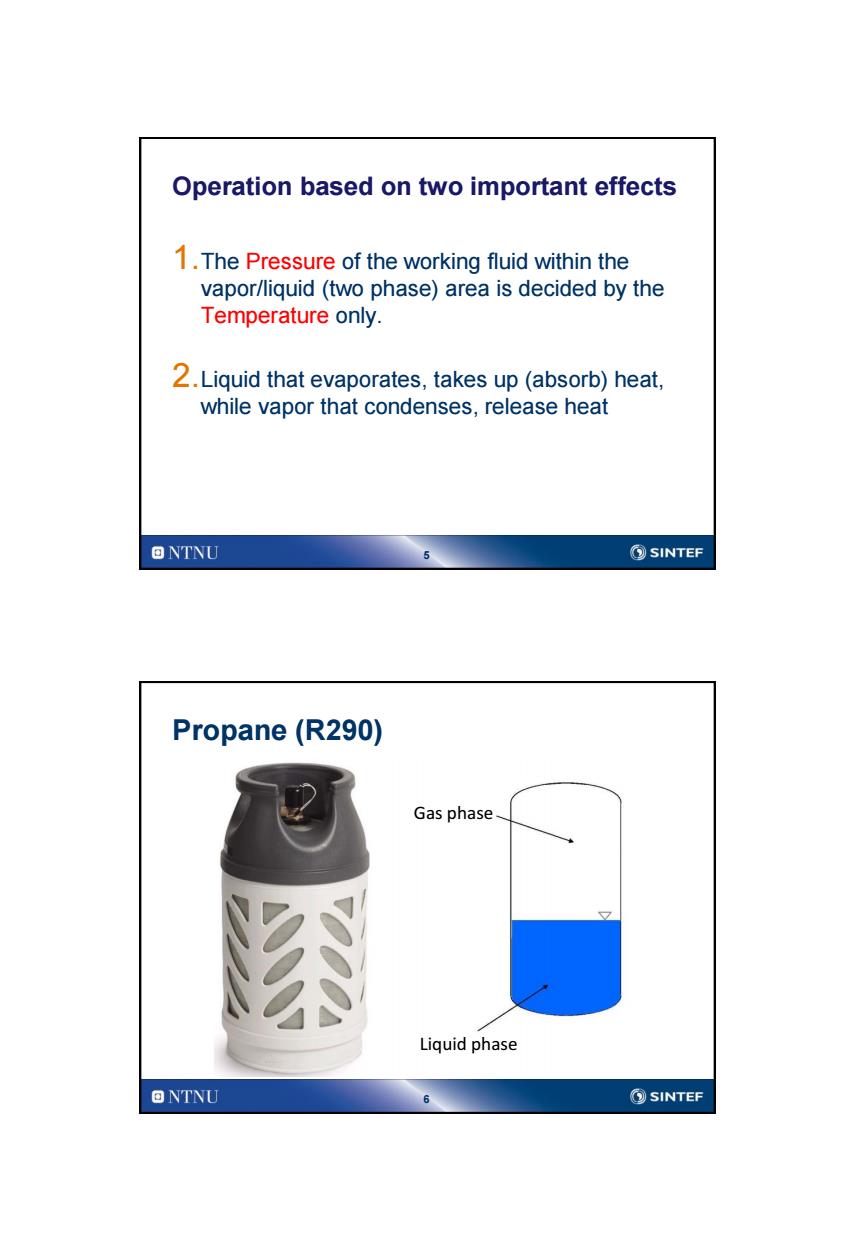
5 Operation based on two important effects 1.The Pressure of the working fluid within the vapor/liquid (two phase) area is decided by the Temperature only. 2.Liquid that evaporates, takes up (absorb) heat, while vapor that condenses, release heat 6 Propane (R290) Gas phase Liquid phase

Saturation pressure for propane 18 14 Propane saturation pressure 公 (metningstrykk) 10 'oinssold 8 vaeske 6 damp 2 0 40 20 0 20 40 6( Temperature,c ONTNU ②SINTEF Refrigeration systems Temperature-Pressures in the system tamb=+20℃ Pc Condenser Pcmin Pc.tc VExpansion valve Po.to Compressor Pomax Po Evaporator Q 4030-20-10010203040 tR=-20℃ Saturation temperature,taC] ONTNU ⑤SINTEF
7 Saturation pressure for propane 8 Refrigeration systems Temperature – Pressures in the system Condenser Evaporator pC , tC p0 , t0 𝑄 0 𝑄 𝐶 tR= -20 oC tamb= +20oC 𝑊 𝐶 Pressure, p [bar] -30 -20 -10 0 p0max Saturation temperature, tsat [ oC] -40 10 20 30 40 p0 pCmin pC Expansion valve Compressor

Working fluids Important properties of working fluids in heat pumps R404AR407C R410AR134a R7171 R2902 R7443 Molar weight 97,6 86,2 72.6 102,2 17,03 44,10 44,01 Boiling point, -46,5 43,8 -51.6 -26,2 -33,3 -42,1 -78,03 1 bar [C] Crit.temp.te[C] 74.4 87,3 72.5 101,1 132,3 96,8 31,1 Crit.Press.Pe[bar] 37,3 46,3 49,5 40.7 113,3 42,5 73.8 Paat,OC [bar] 6,0 5,7 8,0 2,9 4,3 4,8 34,9 △h.0C[kJ/kg] 169 209 221 199 1262 375 231 pn0℃[kgml 1114 1237 1171 1295 639 493 928 Pg,0℃[kg1m 30 20 31 14 4 10 98 t,5,25 bar [C] 55 60 534 77 58 68 GWP[ 3800 1700 2000 1300 0 3 0(1) Poison/flammable No No No No Yes/No No/Yes No 1)Ammonia(NHa) 2)Propane (C3Ha) 3)Carbon dioxside (CO2) 4)35 bar 5)Condensing temperature ONTNU ②SINTEF Working fluids-properties Example 2-Saturation curve for ammonia(NHa) 120 Critical point 夏w (132,2℃113,3a Linear axis- 80 60 uopeines (78.5*C,40 bar) 40 62℃,25am 20 NBP 633,3C,1013ba 0 -60 30 030 60 90 120 150 Saturation temperature,t [C] 回NTNU 10 ⑤SINTEF
9 Working fluids Important properties of working fluids in heat pumps R404A R407C R410A R134a R7171 R2902 R7443 Molar weight 97,6 86,2 72,6 102,2 17,03 44,10 44,01 Boiling point, 1 bar [°C] -46,5 -43,8 -51,6 -26,2 -33,3 -42,1 -78,03 Crit. temp. tc [°C] 74,4 87,3 72,5 101,1 132,3 96,8 31,1 Crit. Press. pc [bar] 37,3 46,3 49,5 40,7 113,3 42,5 73,8 psat, 0°C [bar] 6,0 5,7 8,0 2,9 4,3 4,8 34,9 Dhf , 0°C [kJ/kg] 169 209 221 199 1262 375 231 rv , 0°C [kg/m3 ] 1114 1237 1171 1295 639 493 928 rg , 0°C [kg/m3 ] 30 20 31 14 4 10 98 tk 5 , 25 bar [°C] 55 60 534 77 58 68 * GWP [-] 3800 1700 2000 1300 0 3 0 (1) Poison/flammable No No No No Yes/No No/Yes No 1) Ammonia (NH3 ) 2) Propane (C3H8 ) 3) Carbon dioxside (CO2 ) 4) 35 bar 5) Condensing temperature 10 Working fluids – properties Example 2 – Saturation curve for ammonia (NH3 ) Linear axis Saturation temperature, t [oC] Saturation pressure, p [bar] Critical point

Saturation pressure different working fluids Connection between saturation pressure and temperature -。-R744 一-R410A 8 -=-R-717 ◇-R-407C R744 -R22 —R-280 ---R-134阳 -R-12 R717 4 R410A R290 TrykkA R134a 3 R407C Trykk B Temperature A 40 20 0 20 40 60 80 100 Saturation temperature [C] ONTNU 11 ②SINTEF Ammonia,R717 (Diagram from CoolPack) a10
11 Saturation pressure different working fluids Connection between saturation pressure and temperature R744 R717 R134a R407C R410A R290 Saturation temperature [°C] Saturation pressure [MPa] Trykk A Temperature A Trykk B Temperature B 12 Ammonia, R717 (Diagram from CoolPack)

Processes in log P-h diagram Critical point s-constant Isentropic Liquid Isotherm,t÷constant Boiling point curve Vapor fraction Isochoric v constant Gas x=constant (vapor) 0=x Two phase area eno quod Med Specific enthalpy,h(kJ/kg) ONTNU 13 ②SINTEF Ammonia,R717 (Diagram from CoolPack) “司
13 Critical point Isotherm, t = constant Specific enthalpy, h (kJ/kg) Pressure, p (bar) Gas (vapor) Liquid Two phase area Processes in log P-h diagram 14 Ammonia, R717 (Diagram from CoolPack)

Processes in Ts-diagram p=constant Critical point Liquid Gas (vapor) Boiling point curve isochoric v=constant Dew point curve Isenthalpic h=constant X=0 Isenthalpic h±constant X=1 Two phase area Specific entropy,s(J/kgK) ONTNU 15 ②SINTEF Ts diagram for a heating process at constant pressure p=constant 2 1 do Tds 2 Q=T ds S2 Entropy,S [J/K] 回NTNU ⑤SINTEF
15 Specific entropy, s (J/kgK) Temperature, T (K) Liquid Two phase area Gas (vapor) Isenthalpic h = constant Critical point Processes in Ts-diagram Isenthalpic h = constant 16 Ts diagram for a heating process at constant pressure 1 2 p = constant Entropy, S [J/K] Temperature, T [K] T2 T1 S1 S2 dS 𝑑𝑄 = 𝑇𝑑𝑆 𝑄 = 𝑇 𝑑𝑆 2 1
Carnot process 4 3 mb Tamb =TH Wc Tr TR=TL 2 Qo △S Entropy,S [J/K] ONTNU 17 ②SINTEF Minimum work of a refrigeration Carnot process Coefficient Of Performance(power factor) TLAS COP= Q Wc (TH-T)△S 个y COP =TH -TL Minimum work TH-TL Wc Qo- H-T)=Q (TH-TL) TH ONTNU 18 SINTEF
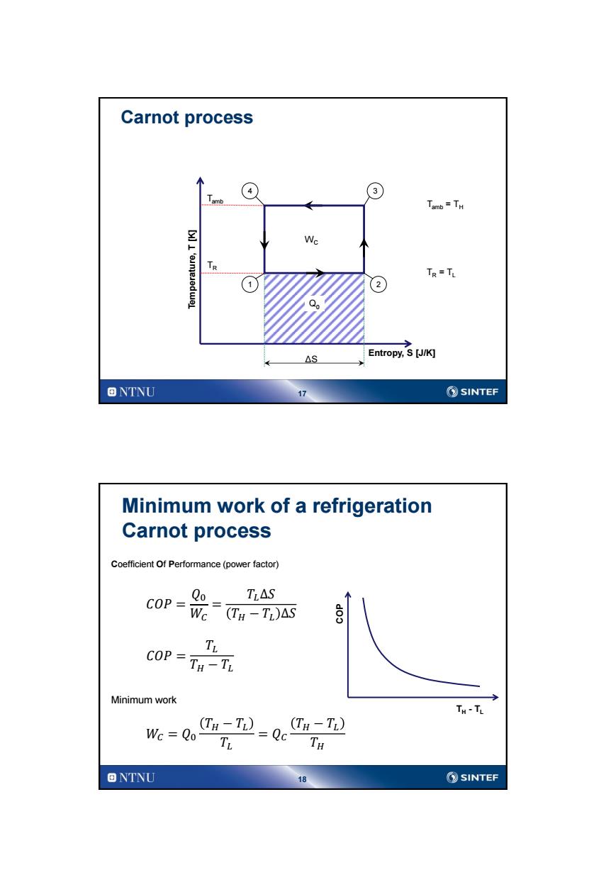
17 Carnot process 1 3 Entropy, S [J/K] Temperature, T [K] Tamb TR Q0 4 2 WC ΔS Tamb = TH TR = TL 18 Minimum work of a refrigeration Carnot process 𝐶𝑂𝑃 = 𝑄0 𝑊𝐶 = 𝑇𝐿∆𝑆 𝑇𝐻 − 𝑇𝐿 ∆𝑆 Coefficient Of Performance (power factor) 𝐶𝑂𝑃 = 𝑇𝐿 𝑇𝐻 − 𝑇𝐿 Minimum work 𝑊𝐶 = 𝑄0 𝑇𝐻 − 𝑇𝐿 𝑇𝐿 = 𝑄𝐶 𝑇𝐻 − 𝑇𝐿 𝑇𝐻 COP TH - TL
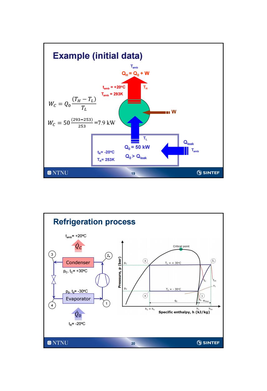
Example (initial data) QH=Qo+W tanb=+20o℃ Tamb=293K Wc Qo (TH-TL) TL W We=50293-253=79kw 253 Qo=50 kW tg=-20℃ TR=253K Qo>Qleak ONTNU 19 SINTEF Refrigeration process tmb=+20℃ Qa Critical point 3 Condenser ③ Tc=+30C ② Pc,te=+30℃ Pnt=-30℃ Po Tm=-30℃ ④ Evaporator ) 1) hs=h Specific enthalpy,h(kJ/kg) tR=-20℃ ONTNU 20 SINTEF
19 TH TL QH = Q0 + W Q0 > Qleak W tR= -20oC Tamb Tamb Example (initial data) Qleak tamb = +20oC 𝑊𝐶 = 𝑄0 𝑇𝐻 − 𝑇𝐿 𝑇𝐿 Q0 = 50 kW 𝑊𝐶 = 50 293−253 253 =7.9 kW TR= 253K Tamb = 293K 20 Refrigeration process Condenser Evaporator 4 2s 3 1 pC , tC= +30oC p0 , t0= -30oC 𝑄 0 𝑄 𝐶 tR= -20 oC tamb= +20oC