§5 Voltammetry §5-1 Basic principle of polarograpy Voltammetry A group of analytical methods based on determining current flow – voltage curve during electrolysis Several types of methods based on Electrode type How the potential is applied How the current is measured
§5 Voltammetry §5-1 Basic principle of polarograpy Voltammetry A group of analytical methods based on determining current flow – voltage curve during electrolysis Several types of methods based on Electrode type How the potential is applied How the current is measured
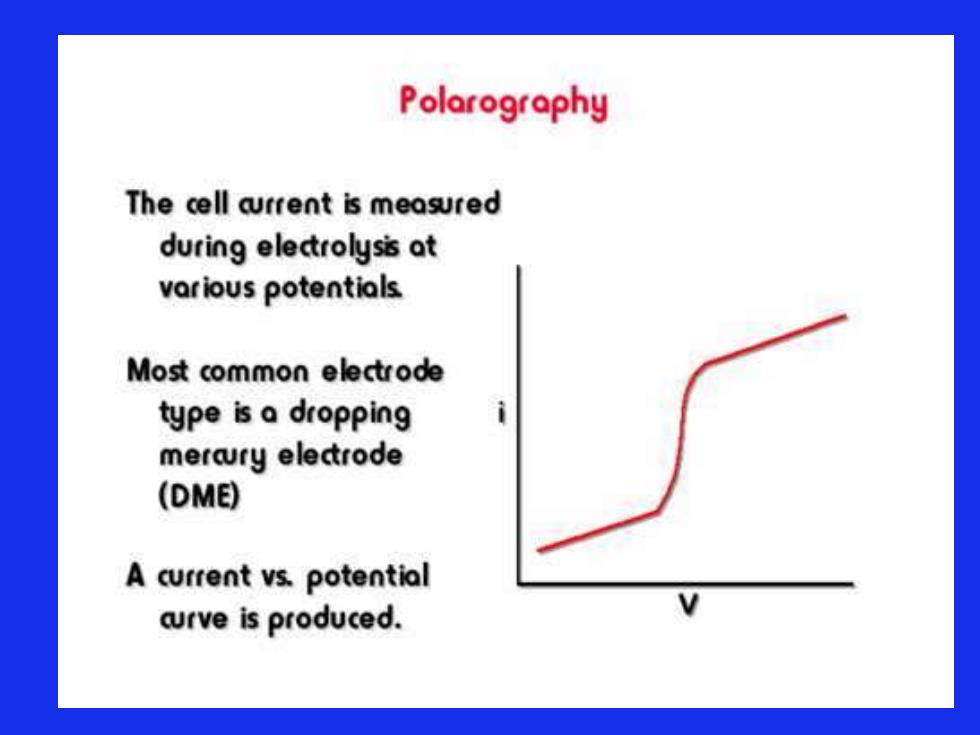
Polarography The cell arrent is measured during electrolysis at various potentials Most common electrode type is a dropping mercury electrode (DME) A current vs.potential aurve is produced
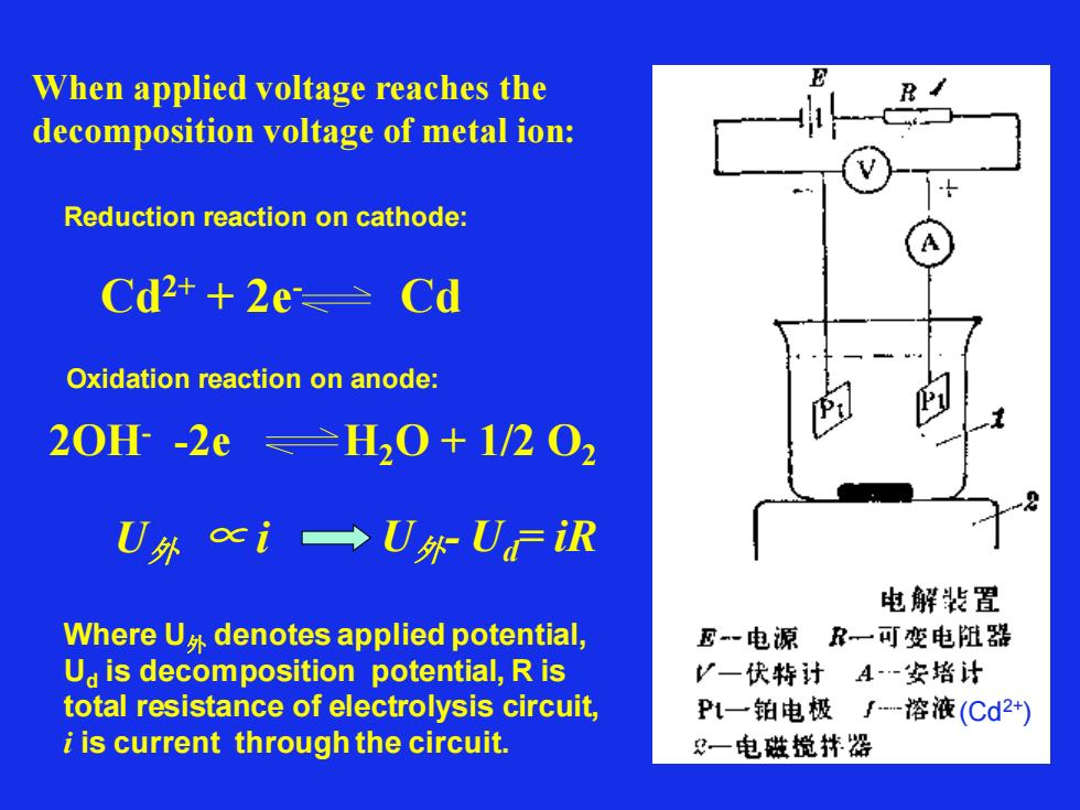
When applied voltage reaches the decomposition voltage of metal ion: Reduction reaction on cathode: Cd2+ + 2e- Cd Oxidation reaction on anode: 2OH- -2e H2O + 1/2 O2 U外 ∝ i Where U外 denotes applied potential, Ud is decomposition potential, R is total resistance of electrolysis circuit, i is current through the circuit. U外- Ud= iR (Cd2+)
When applied voltage reaches the decomposition voltage of metal ion: Reduction reaction on cathode: Cd2+ + 2e- Cd Oxidation reaction on anode: 2OH- -2e H2O + 1/2 O2 U外 ∝ i Where U外 denotes applied potential, Ud is decomposition potential, R is total resistance of electrolysis circuit, i is current through the circuit. U外- Ud= iR (Cd2+)
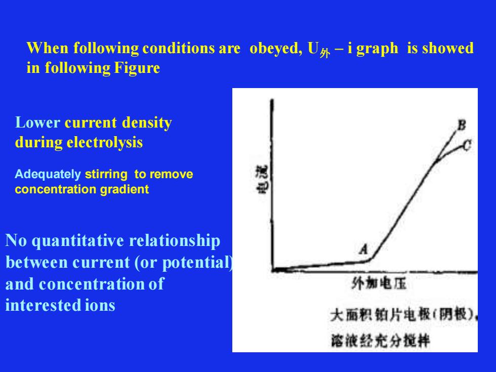
When following conditions are obeyed, U外 – i graph is showed in following Figure Lower current density during electrolysis Adequately stirring to remove concentration gradient No quantitative relationship between current (or potential) and concentration of interested ions
When following conditions are obeyed, U外 – i graph is showed in following Figure Lower current density during electrolysis Adequately stirring to remove concentration gradient No quantitative relationship between current (or potential) and concentration of interested ions
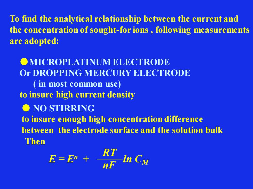
To find the analytical relationship between the current and the concentration of sought-for ions , following measurements are adopted: ●MICROPLATINUM ELECTRODE Or DROPPING MERCURY ELECTRODE ( in most common use) to insure high current density ● NO STIRRING to insure enough high concentration difference between the electrode surface and the solution bulk Then E = Eo + ln CM RT nF
To find the analytical relationship between the current and the concentration of sought-for ions , following measurements are adopted: ●MICROPLATINUM ELECTRODE Or DROPPING MERCURY ELECTRODE ( in most common use) to insure high current density ● NO STIRRING to insure enough high concentration difference between the electrode surface and the solution bulk Then E = Eo + ln CM RT nF
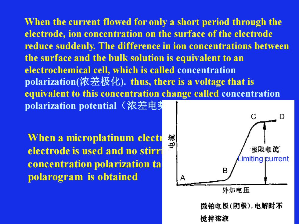
When the current flowed for only a short period through the electrode, ion concentration on the surface of the electrode reduce suddenly. The difference in ion concentrations between the surface and the bulk solution is equivalent to an electrochemical cell, which is called concentration polarization(浓差极化). thus, there is a voltage that is equivalent to this concentration change called concentration polarization potential(浓差电势) When a microplatinum electrode or dropping mercury electrode is used and no stirring is carried out, concentration polarization takes place soon, following polarogram is obtained Limiting current A B C D
When the current flowed for only a short period through the electrode, ion concentration on the surface of the electrode reduce suddenly. The difference in ion concentrations between the surface and the bulk solution is equivalent to an electrochemical cell, which is called concentration polarization(浓差极化). thus, there is a voltage that is equivalent to this concentration change called concentration polarization potential(浓差电势) When a microplatinum electrode or dropping mercury electrode is used and no stirring is carried out, concentration polarization takes place soon, following polarogram is obtained Limiting current A B C D
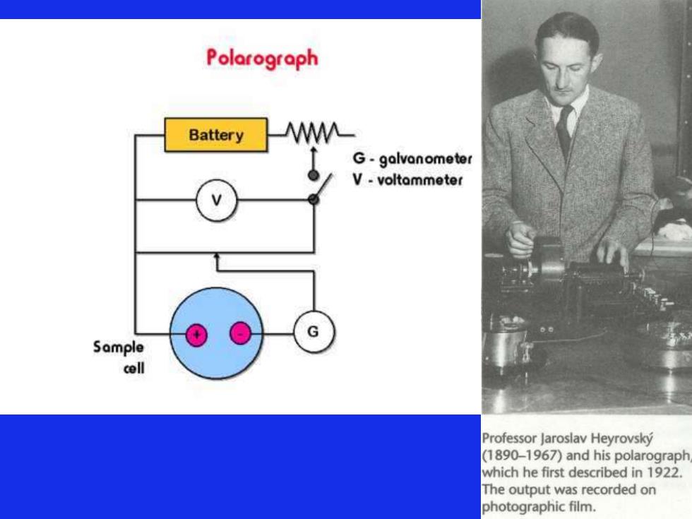
Polarograph Battery M G-galvanometer V-voltammeter Sample cell Professor Jaroslav Heyrovsky (1890-1967)and his polarograph which he first described in 1922. The output was recorded on photographic film
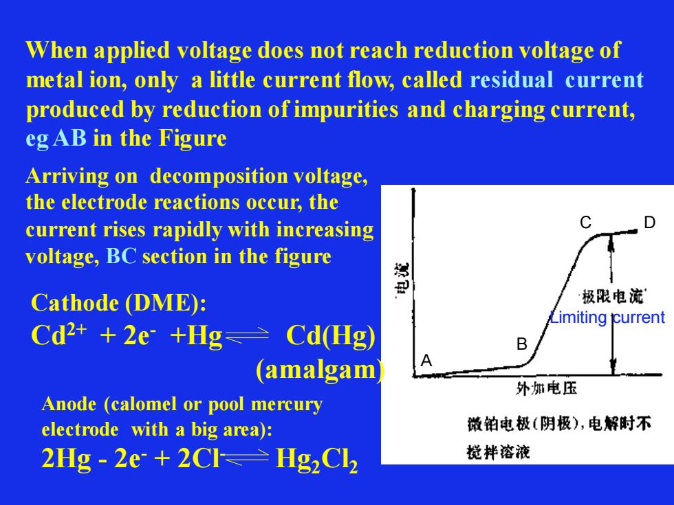
When applied voltage does not reach reduction voltage of metal ion, only a little current flow, called residual current produced by reduction of impurities and charging current, eg AB in the Figure Limiting current A B C D Arriving on decomposition voltage, the electrode reactions occur, the current rises rapidly with increasing voltage, BC section in the figure Cathode (DME): Cd2+ + 2e- +Hg Cd(Hg) (amalgam) Anode (calomel or pool mercury electrode with a big area): 2Hg - 2e- + 2Cl- Hg2Cl2
When applied voltage does not reach reduction voltage of metal ion, only a little current flow, called residual current produced by reduction of impurities and charging current, eg AB in the Figure Limiting current A B C D Arriving on decomposition voltage, the electrode reactions occur, the current rises rapidly with increasing voltage, BC section in the figure Cathode (DME): Cd2+ + 2e- +Hg Cd(Hg) (amalgam) Anode (calomel or pool mercury electrode with a big area): 2Hg - 2e- + 2Cl- Hg2Cl2

When it reaches C point voltage, due to concentration polarization, the current arrives at a limiting value and does not rise markedly, called limiting current, consisting of residual current and diffusion current 极谱波可以用i~ U外表示曲线表示,也可以用i ~ Ede曲线来表示,从下 面的讨论可以看出,二者是基本重合的。 U = ( ESCE -Ede ) + i R ∵ i and R are very little in polarographic electrolysis U = ESCE -Ede = -Ede( vs. SCE) To remove completely influence of iR, three electrode system is usually used
When it reaches C point voltage, due to concentration polarization, the current arrives at a limiting value and does not rise markedly, called limiting current, consisting of residual current and diffusion current 极谱波可以用i~ U外表示曲线表示,也可以用i ~ Ede曲线来表示,从下 面的讨论可以看出,二者是基本重合的。 U = ( ESCE -Ede ) + i R ∵ i and R are very little in polarographic electrolysis U = ESCE -Ede = -Ede( vs. SCE) To remove completely influence of iR, three electrode system is usually used
Very little oscillation
Very little oscillation