
5锁存器和触发器 (Latch Flip-Flops) 5.1引言(ntroduction) 5.2锁存器(Latch) 5.3触发器(Fip-Flops)的结构与工作原理 5.4触发器的逻辑功能 (Logic Function of Flip-Flop)
5.2 锁存器(Latch) 5.3 触发器(Flip-Flops)的结构与工作原理 5.4 触发器的逻辑功能 (Logic Function of Flip-Flop) 5.1 引言(Introduction) 5 锁存器和触发器 (Latch & Flip-Flops)
5.1 Introduction ◆Review *Combinational Circuits(组合电路) No Storage,No Feedback. The output level is at all times dependent on the combination of input levels. *Sequential Circuits(时序电路) Storage involved,Feedback involved The output depends not only on the present value of inputs,but also on past inputs
• No Storage, No Feedback. • The output level is at all times dependent on the combination of input levels. •Storage involved, Feedback involved •The output depends not only on the present value of inputs, but also on past inputs. 5.1 Introduction ◆Review Combinational Circuits (组合电路) Sequential Circuits (时序电路)
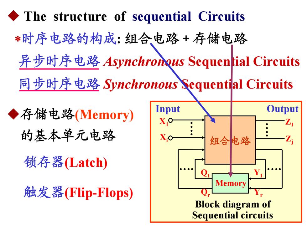
The structure of sequential Circuits *时序电路的构成:组合电路+存储电路 异步时序电路Asynchronous Sequential Circuits 同步时序电路Synchronous&equential Circuits ◆存储电路(Memory) Input Output Xo 的基本单元电路 。 组合电路 锁存器(Latch) Q Memory 触发器(FIip-Flops)) Block diagram of Sequential circuits
组合电路 Memory Block diagram of Sequential circuits . . . . X1 Xi Z1 Zj Q1 Qr Y1 Yr Input Output ◆ The structure of sequential Circuits 异步时序电路 Asynchronous Sequential Circuits 同步时序电路 Synchronous Sequential Circuits 时序电路的构成: 组合电路+存储电路 ◆存储电路(Memory) 的基本单元电路 锁存器(Latch) 触发器(Flip-Flops)
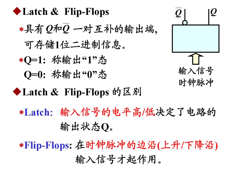
◆Latch&Flip-Flops *具有Q和Q一对互补的输出端, 可存储1位二进制信息。 *Q=1:称输出“1”态 Q=0:称输出“0”态 输入信号 时钟脉冲 ◆Latch&Flip-Flops的区别 *Latch:输入信号的电平高/低决定了电路的 输出状态Q。 *FIip-Flops:在时钟脉冲的边沿(上升/下降沿) 输入信号才起作用
◆Latch & Flip-Flops 具有 一对互补的输出端, 可存储1位二进制信息。 和QQ Q=1: 称输出“1”态 Q=0: 称输出“0”态 ◆Latch & Flip-Flops 的区别 Latch:输入信号的电平高/低决定了电路的 输出状态Q。 Flip-Flops: 在时钟脉冲的边沿(上升/下降沿) 输入信号才起作用。 Q Q 输入信号 时钟脉冲
The Characteristics of Latch F-F *有两个能够保持的稳定状态,分别用来表示逻辑 0和逻辑1(having two retainable stable states which represent 0 and 1 respectively ) *在输入信号作用下,可从一种状态翻转到另一种 状态;在输入信号取消后,能保存获得的新状态. changing from one state to the other under certain inputs and residing in the new state indefinitely even without the prior inputs)
◆The Characteristics of Latch & F-F 有两个能够保持的稳定状态, 分别用来表示逻辑 0和逻辑1 ( having two retainable stable states which represent 0 and 1 respectively ). 在输入信号作用下, 可从一种状态翻转到另一种 状态; 在输入信号取消后, 能保存获得的新状态. ( changing from one state to the other under certain inputs and residing in the new state indefinitely even without the prior inputs)
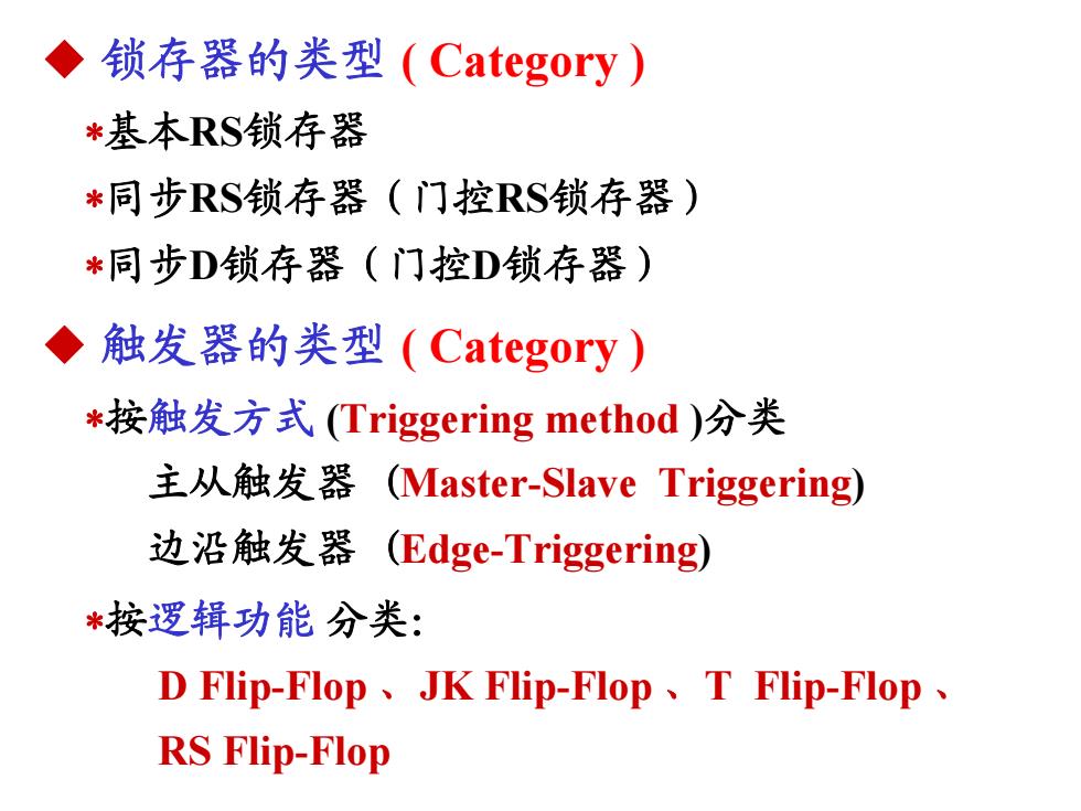
◆锁存器的类型(Category) *基本RS锁存器 *同步RS锁存器(门控RS锁存器) *同步D锁存器(门控D锁存器) ◆) 触发器的类型(Category) *按触发方式(Triggering method)分类 主从触发器(Master-Slave Triggering) 边沿触发器(Edge-Triggering) *按逻辑功能分类: D Flip-Flop、JK Flip-Flop、T Flip-Flop、 RS Flip-Flop
◆ 锁存器的类型 ( Category ) 基本RS锁存器 同步RS锁存器(门控RS锁存器) 同步D锁存器(门控D锁存器) ◆ 触发器的类型 ( Category ) 按触发方式 (Triggering method )分类 主从触发器 (Master-Slave Triggering) 边沿触发器 (Edge-Triggering) 按逻辑功能 分类: D Flip-Flop 、JK Flip-Flop 、T Flip-Flop 、 RS Flip-Flop
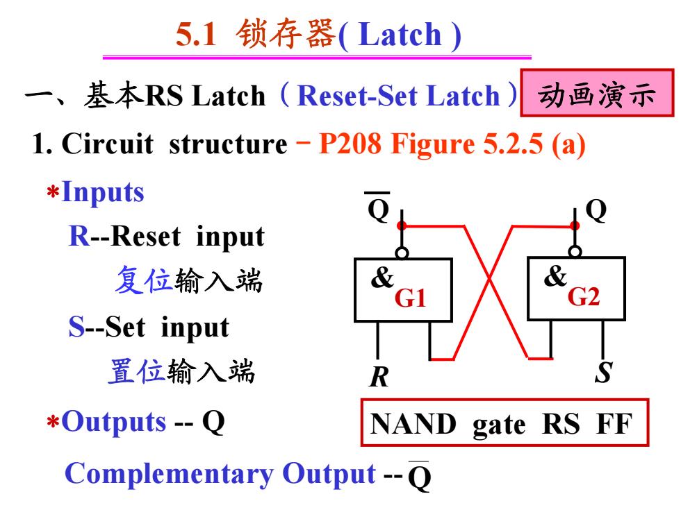
5.1锁存器(Latch) 一、 基本RS Latch(Reset-.Set Latch) 动画演示 1.Circuit structure-P208 Figure 5.2.5 (a) *Inputs R-Reset input 复位输入端 & G2 S-Set input 置位输入端 R *Outputs -Q NAND gate RS FF Complementary Output-O
5.1 锁存器( Latch ) 一、基本RS Latch(Reset-Set Latch) Q R S Q 1. Circuit structure-P208 Figure 5.2.5 (a) Inputs R-Reset input 复位输入端 S-Set input 置位输入端 Outputs - Q Complementary Output -Q & G1 & G2 NAND gate RS FF 动画演示
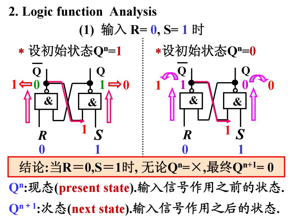
2.Logic function Analysis (1)输入R=0,S=1时 *设初始状态Q=1 *设初始状态Q=0 R R 0 结论:当R=0,S=1时,无论Q=X,最终Q+1=0 Q:现态(present state).输入信号作用之前的状态. Qn+l:次态(next state).输入信号作用之后的状态
1 0 1 0 0 1 设初始状态Qn=1 0 1 Q Q & & R S 设初始状态Qn=0 Q Q & & 1 0 R S 1 1 结论:当R=0,S=1时, 无论Qn=×,最终Qn+1= 0 2. Logic function Analysis (1) 输入 R= 0, S= 1 时 Qn:现态(present state).输入信号作用之前的状态. Qn+1:次态(next state).输入信号作用之后的状态. 0 1
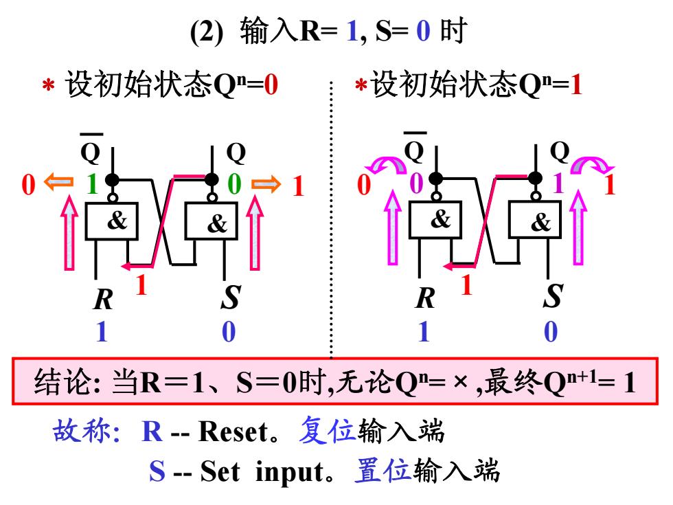
(2)输入R=1,S=0时 *设初始状态Q=0 *设初始状态Q=1 0 1 0 结论:当R=1、S=0时,无论Q=×,最终Q+1=1 故称:R-Reset。复位输入端 S-Set input。置位输入端
0 1 0 1 1 1 结论: 当R=1、S=0时,无论Qn=×,最终Qn+1= 1 1 0 Q Q & & R S Q Q & & 0 1 R S 设初始状态Qn=0 设初始状态Qn=1 (2) 输入R= 1, S= 0 时 故称:R - Reset。复位输入端 S - Set input。置位输入端 1 0 1 0
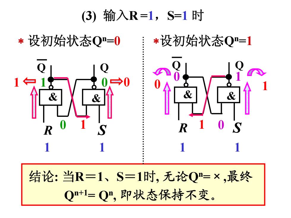
(3) 输入R=1,S=1时 *设初始状态Q=0 *设初始状态Q=1 白1 1 1 结论:当R=1、S=1时,无论Q=×,最终 Q+1=Q”,即状态保持不变
0 0 1 1 1 0 0 1 结论: 当R=1、S=1时, 无论Qn=×,最终 Qn+1= Qn, 即状态保持不变。 (3) 输入R =1,S=1 时 Q Q & & R S 1 0 Q Q & & R S 0 1 设初始状态Qn=0 设初始状态Qn=1 1 1 1 1