
2运算放大器 Operational Amplifier (OP-Amp) 2.0引言(Introduction) 2.1集成电路运算放大器(ICOp-Ap) 2.2理想运算放大器(Ideal Op-Amp) 2.3基本线性运算放大电路 2.4同相输入和反相输入放大电路 的其它应用
2.1 集成电路运算放大器 (IC Op-Amp ) 2.2 理想运算放大器 (Ideal Op-Amp ) 2.3 基本线性运算放大电路 2.4 同相输入和反相输入放大电路 的其它应用 Operational Amplifier (OP-Amp) 2.0 引言(Introduction)
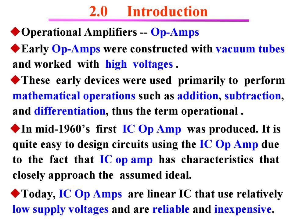
2.0 Introduction Operational Amplifiers-Op-Amps Early Op-Amps were constructed with vacuum tubes and worked with high voltages. These early devices were used primarily to perform mathematical operations such as addition,subtraction, and differentiation,thus the term operational. In mid-1960's first IC Op Amp was produced.It is quite easy to design circuits using the IC Op Amp due to the fact that IC op amp has characteristics that closely approach the assumed ideal. Today,IC Op Amps are linear IC that use relatively low supply voltages and are reliable and inexpensive
◆In mid-1960’s first IC Op Amp was produced. It is quite easy to design circuits using the IC Op Amp due to the fact that IC op amp has characteristics that closely approach the assumed ideal. 2.0 Introduction ◆Operational Amplifiers - Op-Amps ◆Early Op-Amps were constructed with vacuum tubes and worked with high voltages . ◆These early devices were used primarily to perform mathematical operations such as addition, subtraction, and differentiation, thus the term operational . ◆Today, IC Op Amps are linear IC that use relatively low supply voltages and are reliable and inexpensive
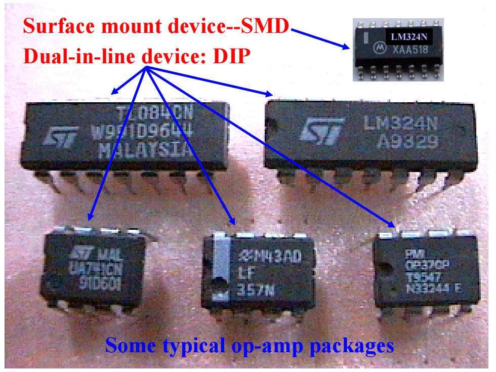
Surface mount device-SMD LM324N Dual-in-line device:DIP ②XAA518 084 324N A9329 利42 F 35用 Some typical op-amp packages
LM324N Some typical op-amp packages Surface mount device-SMD Dual-in-line device: DIP
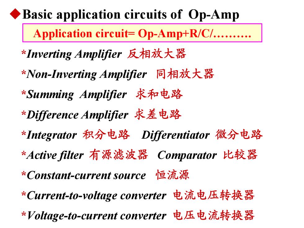
Basic application circuits of Op-Amp Application circuit=Op-Amp+R/C/. *Inverting Amplifier反相放大器 *Non-Inverting Amplifier同相放大器 *Summing Amplifier求和电路 *Difference Amplifier求差电路 *Integrator积分电路Differentiator微分电路 *Active filter有源滤波器 Comparator比较器 Constant-current source 恒流源 *Current-to-voltage converter电流电压转换器 *Voltage-to-current converter电压电流转换器
◆Basic application circuits of Op-Amp *Inverting Amplifier 反相放大器 *Non-Inverting Amplifier 同相放大器 *Summing Amplifier 求和电路 *Difference Amplifier 求差电路 *Active filter 有源滤波器 Comparator 比较器 *Integrator 积分电路 Differentiator 微分电路 *Constant-current source 恒流源 *Current-to-voltage converter 电流电压转换器 *Voltage-to-current converter 电压电流转换器 Application circuit= Op-Amp+R/C/
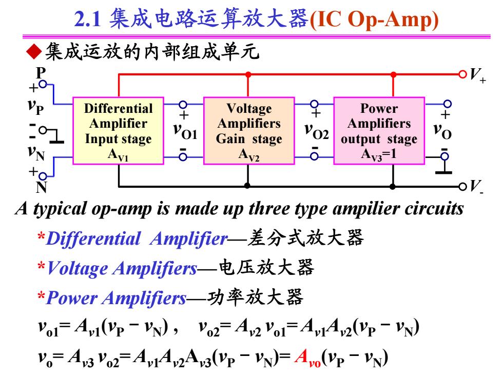
2.1集成电路运算放大器(ICOp-Amp) ◆集成运放的内部组成单元 P Differential Voltage 9 Power Amplifier Amplifiers Input stage Gain stage vo2 Amplifiers output stage N Av2 Av3=1 A typical op-amp is made up three type ampilier circuits *Differential Amplifier-一差分式放大器 *Voltage Amplifiers-一电压放大器 *Power Amplifiers-一功率放大器 Vo=AvI(VP -VN),Vo2=Av2 Vo=Av4Av2(VP -VN) Vo=Av3 P02=Av14v2Av3(Vp-VN)=Avo(VP-EN)
2.1 集成电路运算放大器(IC Op-Amp) ◆集成运放的内部组成单元 + - + - + - Differential Amplifier Input stage AV1 Voltage Amplifiers Gain stage AV2 Power Amplifiers output stage AV3 =1 + - + - vP vN vO1 vO2 vO P N V+ V - A typical op-amp is made up three type ampilier circuits *Differential Amplifier—差分式放大器 *Voltage Amplifiers—电压放大器 *Power Amplifiers—功率放大器 vo1 = Av1 (vP-vN ) , vo2 = Av2 vo1 = Av1 Av2 (vP-vN ) vo = Av3 vo2 = Av1 Av2 Av3 (vP-vN )= Avo (vP-vN )
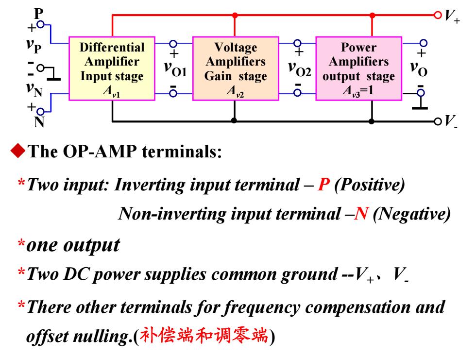
P oV: VP Differential Voltage Power 0 Amplifier Amplifiers Input stage Vo! Gain stage vo2 Amplifiers output stage A3-1 ◆The OP-AMP terminals: *Two input:Inverting input terminal-P(Positive) Non-inverting input terminal-N (Negative) *one output *Two DC power supplies common ground-V V. There other terminals for frequency compensation and of你et nulling.(补偿端和调零端)
+ - + - + - Differential Amplifier Input stage Av1 Voltage Amplifiers Gain stage Av2 Power Amplifiers output stage Av3 =1 + - + - vP vN vO1 vO2 vO P N V+ V - ◆The OP-AMP terminals: *Two input: Inverting input terminal – P (Positive) Non-inverting input terminal –N (Negative) *one output *Two DC power supplies common ground -V+、V- *There other terminals for frequency compensation and offset nulling.(补偿端和调零端)
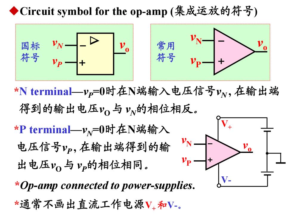
◆Circuit symbol for the op-amp(集成运放的符号) 国标 VN 常用 符号 VP 符号 *N termina一yp=O时在N端输入电压信号yw,在输出端 得到的输出电压'o与'的相位相反。 *P terminal一yw=O时在N端输入 电压信号yp,在输出端得到的输 出电压v与yp的相位相同。 Vp *Op-amp connected to power-supplies. *通常不画出直流工作电源V,和V-
◆Circuit symbol for the op-amp (集成运放的符号) - + vo vN vP 国标 符号 + vN - vP v 常用 o 符号 *N terminal—vP =0时在N端输入电压信号vN , 在输出端 得到的输出电压vO 与 vN的相位相反。 *P terminal—vN =0时在N端输入 电压信号vP , 在输出端得到的输 出电压vO 与 vP的相位相同。 + vN - vP vo V+ V- *Op-amp connected to power-supplies. *通常不画出直流工作电源V+ 和V-
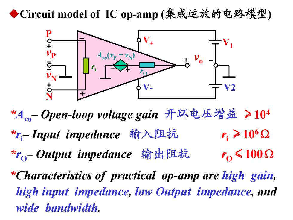
◆Circuit model of IC op-amp(集成运放的电路模型) P Vp-Vy *Ao-Open-loop voltage gain开环电压增益 ≥104 *rInput impedance输入阻抗 r1≥1062 *ro-Output impedance输出阻抗 ro≤1002 *Characteristics of practical op-amp are high gain, high input impedance,low Output impedance,and wide bandwidth
◆Circuit model of IC op-amp (集成运放的电路模型) + - vP ri vo V1 V2 rO Avo (vP -vN ) - + + - - + vN N P + - V+ V- *Avo – Open-loop voltage gain 开环电压增益 *ri – Input impedance 输入阻抗 *rO – Output impedance 输出阻抗 *Characteristics of practical op-amp are high gain, high input impedance, low Output impedance, and wide bandwidth. ≥104 ri ≥106Ω rO ≤100Ω
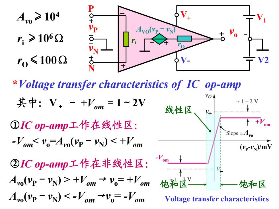
Ao≥104 r≥1062 ro≤1002 V2 Voltage transfer characteristics of IC op-amp 其中:V+-+'om=1~2V ≈1-2V 线性区 V ①ICop-mp工作在线性区: +V om Slope=Avo -Vom+Vm→v。=+Vm 饱和尽y 饱和区 A0(p-)<-Vom→y。=-'om Voltage transfer characteristics
+ - vP ri vo V1 V2 rO AVO (vP -vN ) - + + - - + vN N P + - V+ V- Avo ≥104 ri ≥106Ω rO ≤100Ω (vP -vN )/mV Avo - + Voltage transfer characteristics -Vom +Vom *Voltage transfer characteristics of IC op-amp 其中:V+ - +Vom =1~2V 饱和区 饱和区 ①IC op-amp工作在线性区: -Vom +Vom→ vo = +Vom Avo (vP-vN ) < -Vom→vo = -Vom 线性区
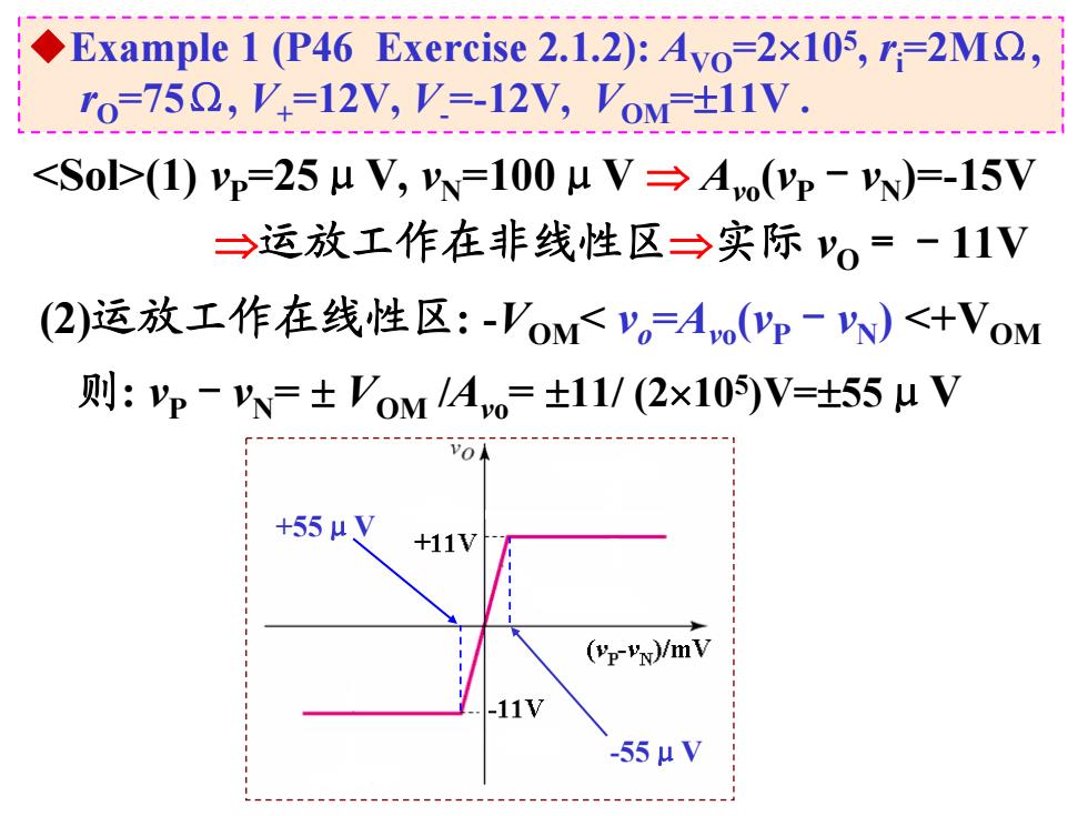
Example 1 (P46 Exercise 2.1.2):Ayo=2x10⁵,r;=2MO, ro=75Q,V=12V,V.=-12V,VoM-+11V. (1)p=25uV,=100μV→Ao(yp-)=-15V →运放工作在非线性区→实际vo=-11V (2)运放工作在线性区:-Vo<V。=A(p-N)<+VoM 则:p-=±VOM LAvO=±11/(2xI0)V=±55LV +55μV +11V (VP-VN)/mV -11V -55μV
◆Example 1 (P46 Exercise 2.1.2): AVO =2105, ri =2MΩ, rO =75Ω, V+ =12V, V- =-12V, VOM =11V . (1) vP =25μV, vN =100μV Avo (vP -vN )=-15V 运放工作在非线性区实际 vO =-11V (2)运放工作在线性区: -VOM < vo =Avo (vP -vN ) <+VOM 则: vP -vN = VOM /Avo = 11/ (2105)V=55μV +55μV -55μV