Earthquake Design of Wood Structures Mar213 1.Seismic Hazards Earthquakes! Earthquakes in Canada
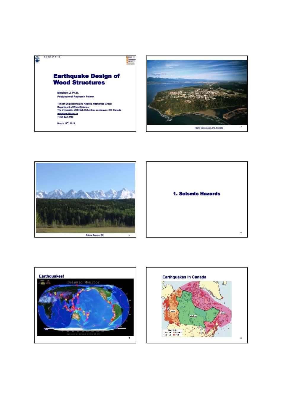
Earthquake Design of Wood Structures Minghao Li, Ph.D. Postdoctoral Research Fellow Timber Engineering and Applied Mechanics Group Department of Wood Science The University of British Columbia, Vancouver, BC, Canada minghao.li@ubc.ca 1-604-822-8185 March 11th, 2013 UBC, Vancouver, BC, Canada 2 Prince George, BC 3 1. Seismic Hazards 4 Earthquakes! 5 Earthquakes in Canada 6
Failure of wood buildings in earthquake quake ground motion Shake table tests on full-scale wood buildinas in Nat Earthquake Loads Equivalent static base shear M V=ST,MEWI(RR。 factor R F+F+F
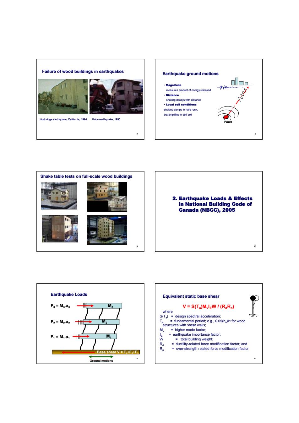
Failure of wood buildings in earthquakes Northridge earthquake, California, 1994 Kobe earthquake, 1995 7 Earthquake ground motions Fault • Magnitude measures amount of energy released • Distance shaking decays with distance • Local soil conditions shaking damps in hard rock, but amplifies in soft soil 8 Shake table tests on full-scale wood buildings 9 2. Earthquake Loads & Effects in National Building Code of Canada (NBCC), 2005 10 Base shear V = F1+F2+F3 Earthquake Loads F1 = M1 .a1 F3 = M3 .a3 F2 = M2 .a2 M3 M1 M2 Ground motions 11 V = S(Ta )Mv IEW / (RdRo ) where S(Ta ) = design spectral acceleration; Ta = fundamental period; e.g., 0.05(hn ) 3/4 for wood structures with shear walls; Mv = higher mode factor; IE = earthquake importance factor; W = total building weight; Rd = ductility-related force modification factor; and Ro = over-strength related force modification factor Equivalent static base shear 12
n曲hargpoctnsa2%n50yeans Dosign spectral acceloration S(T csan Modification factor R cug Modification factorR 5 Earthquake force distribution among stories V-M ≤025V
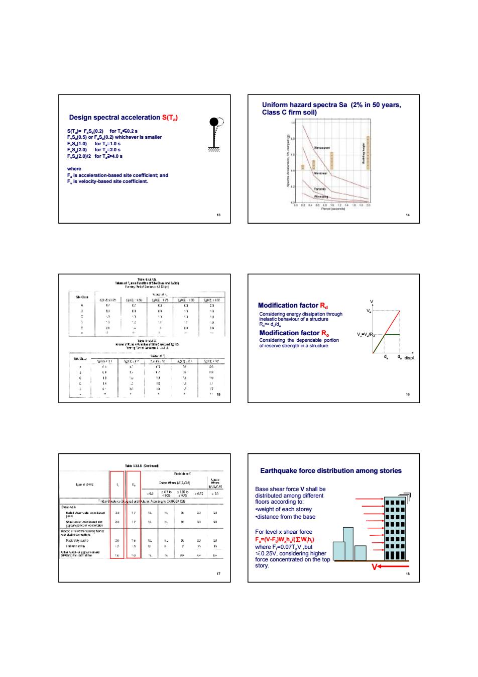
Design spectral acceleration S(Ta ) S(Ta )= FaSa (0.2) for Ta≤0.2 s FvSa (0.5) or FaSa (0.2) whichever is smaller FvSa (1.0) for Ta=1.0 s FvSa (2.0) for Ta=2.0 s FvSa (2.0)/2 for Ta≥4.0 s where Fa is acceleration-based site coefficient; and Fv is velocity-based site coefficient. 13 Uniform hazard spectra Sa (2% in 50 years, Class C firm soil) 14 15 Modification factor Rd V displ. du Ve Vu=Ve /Rd de Considering energy dissipation through inelastic behaviour of a structure Rd≈ du /de Modification factor Ro Considering the dependable portion of reserve strength in a structure 16 17 Earthquake force distribution among stories Base shear force V shall be distributed among different floors according to: •weight of each storey •distance from the base For level x shear force Fx=(V-Ft )Wxhx /(∑Wihi ) where Ft=0.07TaV ,but ≤0.25V, considering higher force concentrated on the top story. V 18
3.1 Shear walls ninSycm 美n Panel-sheathed shear walls Braced shear walls 3.2 Braced frames
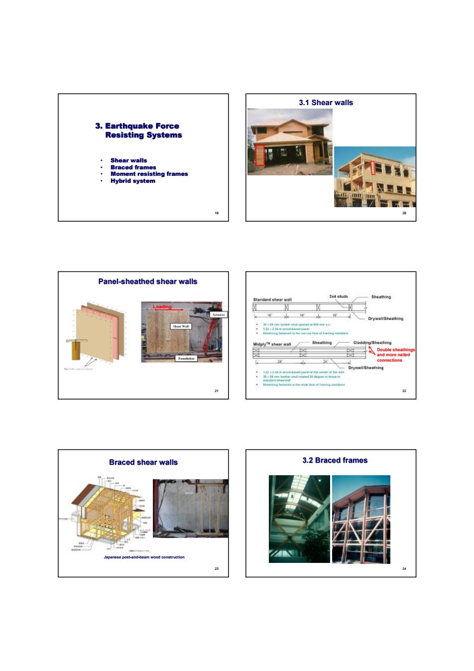
3. Earthquake Force Resisting Systems 19 • Shear walls • Braced frames • Moment resisting frames • Hybrid system 3.1 Shear walls 20 Panel-sheathed shear walls Loading 21 Double sheathings and more nailed connections 22 Braced shear walls Japanese post-and-beam wood construction 23 3.2 Braced frames 24
Partial bracing Full bracing tatic tests on bolted bracing conn Reinforcement of connections 3.3 Moment resisting frames
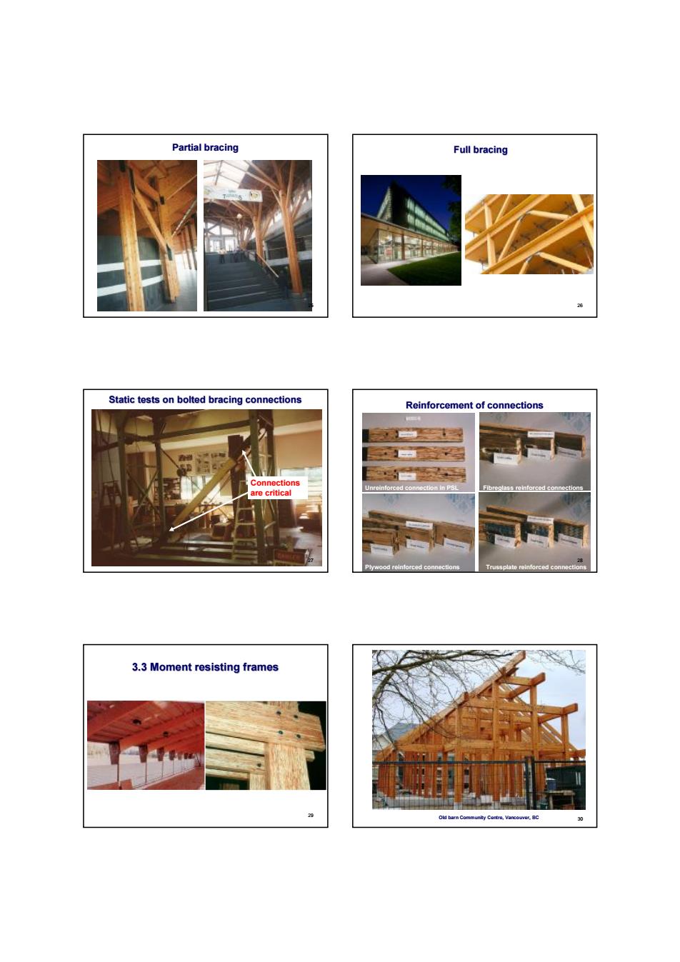
Partial bracing 25 Full bracing 26 Static tests on bolted bracing connections Connections are critical 27 Reinforcement of connections Unreinforced connection in PSL Fibreglass reinforced connections Plywood reinforced connections Trussplate reinforced connections 28 3.3 Moment resisting frames 29 Old barn Community Centre, Vancouver, BC 30

Moment frames in a Shake table test on moment frames 3.4 Hybrid system with st。 Slaphream design [团
Moment frames in a residential building 31 Shake table test on moment frames 32 Tests of reinforced bolted moment connections Unreinforced Reinforced Repaired -70 -60 -50 -40 -30 -20 -10 0 10 20 30 40 50 60 70 -20 -18 -16 -14 -12 -10 -8 -6 -4 -2 0 2 4 6 8 10 12 14 16 18 20 rotation [°] moment [kNm] -70 -60 -50 -40 -30 -20 -10 0 10 20 30 40 50 60 70 -20 -18 -16 -14 -12 -10 -8 -6 -4 -2 0 2 4 6 8 10 12 14 16 18 20 rotation [°] moment [kNm] -70 -60 -50 -40 -30 -20 -10 0 10 20 30 40 50 60 70 -20 -18 -16 -14 -12 -10 -8 -6 -4 -2 0 2 4 6 8 10 12 14 16 18 20 rotation [°] moment [kNm] Self tapping screws Common wood screws and nails 33 3.4 Hybrid system Four-storey student residence apartments (front to back) perforated walls (windows and doors) 34 Seismic strengthening with steel frames steel frame with articulated collectors elevator shaft vertical sleeve for steel frame steel frame 35 4. Shear Walls & Diaphragms in Light-frame Buildings • Shear wall design • Diaphragm design
Typical shear walls and diaphragm ☑ 4.1 Shear Wall Desigr in-plane shear lo Typical failure modes in nailed connection
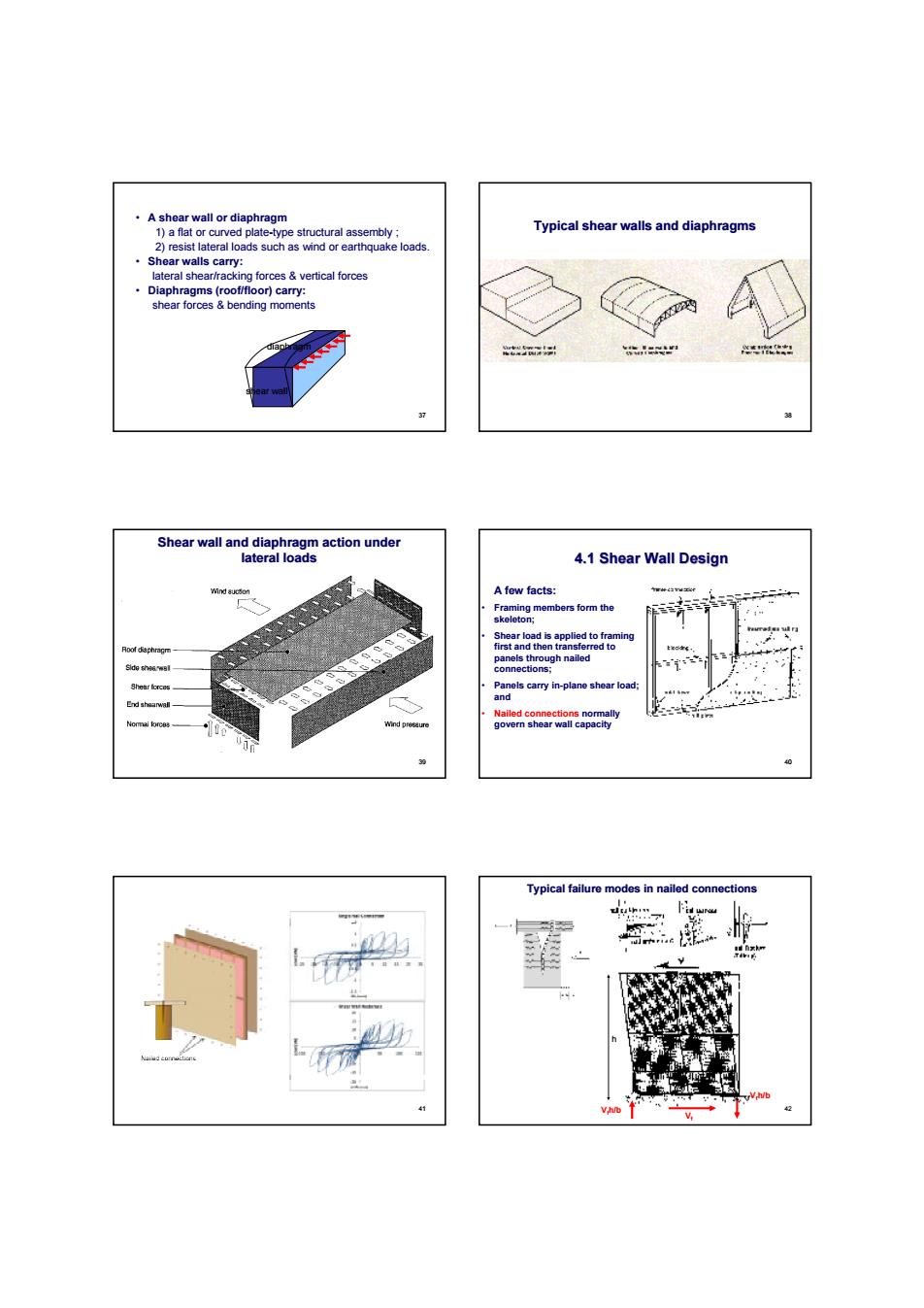
• A shear wall or diaphragm 1) a flat or curved plate-type structural assembly ; 2) resist lateral loads such as wind or earthquake loads. • Shear walls carry: lateral shear/racking forces & vertical forces • Diaphragms (roof/floor) carry: shear forces & bending moments diaphragm shear wall 37 Typical shear walls and diaphragms 38 Shear wall and diaphragm action under lateral loads 39 4.1 Shear Wall Design A few facts: • Framing members form the skeleton; • Shear load is applied to framing first and then transferred to panels through nailed connections; • Panels carry in-plane shear load; and • Nailed connections normally govern shear wall capacity 40 41 Typical failure modes in nailed connections h b Vf Vfh/b Vfh/b 42
Specified shear wall design strength Species adjustment Fully restrained shear walls all-to-foundation hold-down connections Inter-storey hold-down connections n do
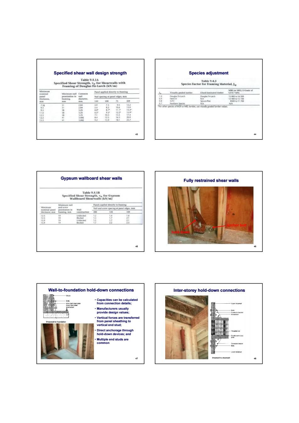
Specified shear wall design strength 43 Species adjustment 44 Gypsum wallboard shear walls 45 Fully restrained shear walls hold-down anchor bolt 46 Wall-to-foundation hold-down connections • Capacities can be calculated from connection details; • Manufacturers usually provide design values; • Vertical forces are transferred from panel sheathing to vertical end stud; • Direct anchorage through hold-down devices; and • Multiple end studs are common 47 Inter-storey hold-down connections 48
Common mistakes in shear wall constr tion Shear wall uplift restraint Partial uplift restraint eld-dew Partial uplift restraint Problems with uplift restraints by anchor bolt t
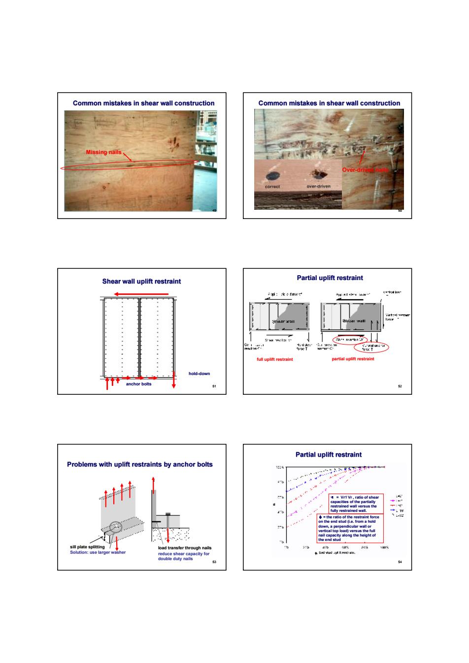
Common mistakes in shear wall construction Missing nails 49 Over-driven nails 50 Common mistakes in shear wall construction Shear wall uplift restraint hold-down anchor bolts horizontal force 51 Partial uplift restraint full uplift restraint partial uplift restraint 52 Problems with uplift restraints by anchor bolts sill plate splitting load transfer through nails Solution: use larger washer reduce shear capacity for double duty nails 53 Partial uplift restraint α = Vr‘/ Vr , ratio of shear capacities of the partially restrained wall versus the fully restrained wall. φ = the ratio of the restraint force on the end stud (i.e. from a hold down, a perpendicular wall or vertical top load) versus the full nail capacity along the height of the end stud 54
The role of blocking members in a shear wal Not efficient 网 Unblocked shear wal Unblocked shear walls c计 Board/lumber sheathed shear walls ompared to panel sheathed
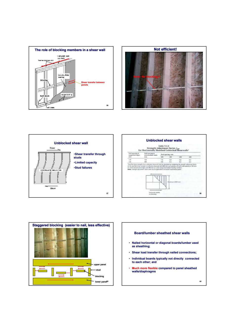
The role of blocking members in a shear wall Shear transfer between panels 55 Not efficient! Note: No blocking !! 56 Unblocked shear wall •Shear transfer through studs •Limited capacity •Stud failures 57 Unblocked shear walls 58 upper panel Staggered blocking (easier to nail, less effective) lower panel stud blocking 59 Board/lumber sheathed shear walls • Nailed horizontal or diagonal boards/lumber used as sheathing; • Shear load transfer through nailed connections; • Individual boards typically not directly connected to each other; and • Much more flexible compared to panel sheathed walls/diaphragms 60