
●●● ●●●● ●●●●● ●●●0 Microwave and RF Design of ●●●●0 ●●●0 ●●●● ●● Wireless Systems Chapter 7 Mixers Dr.Xian Qi Lin 1
Chapter 7 Microwave and RF Design of Wireless Systems Dr. Xian Qi Lin Mixers 1
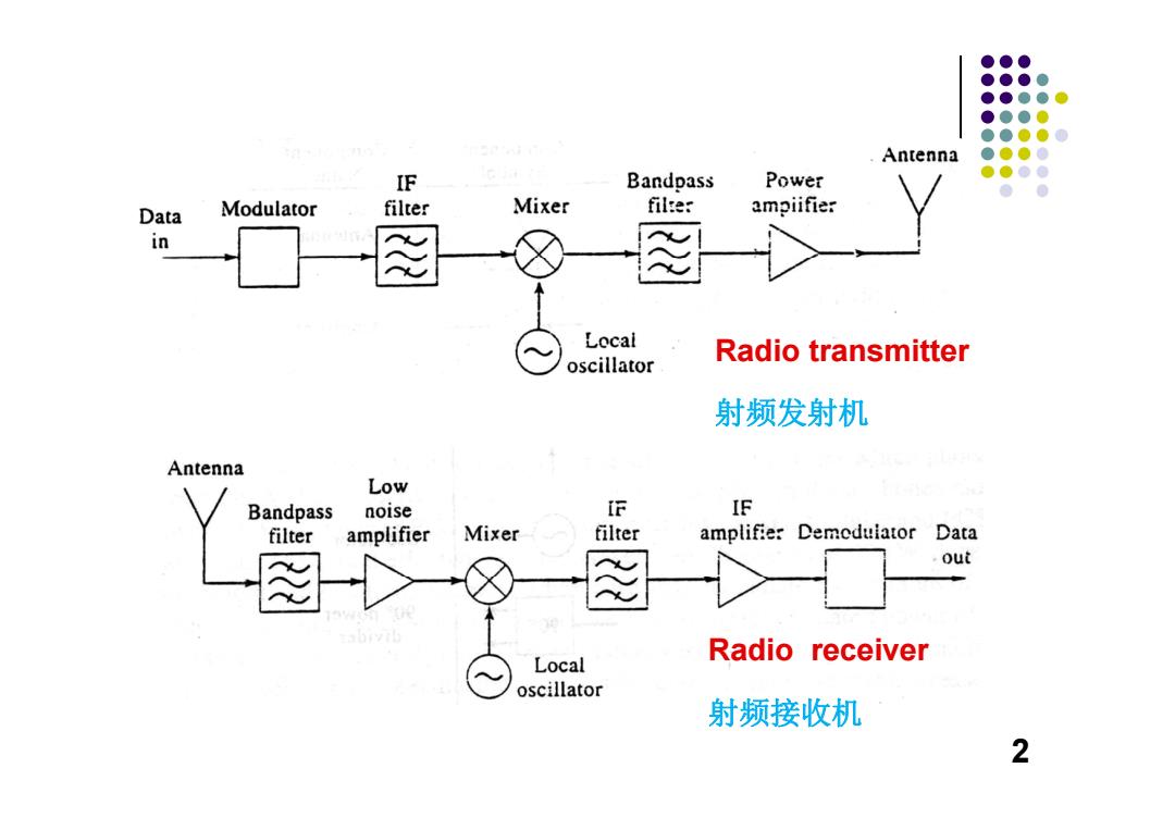
●●● ●●●● ●●●●● ●●●0 ●●●●0 Antenna ●●●● IF Bandpass Power ●●●● ●● Data Modulator filter Mixer filter ampiifier in Local Radio transmitter oscillator 射频发射机 Antenna Low Bandpass noise F IF filter amplifier Mixer filter amplifier Demedulator Data out Local Radio receiver oscillator 射频接收机 2
Radio transmitter 射频发射机 Radio receiver 射频接收机 2
●●● ●●●● ●●●● ●●●● ●●●● ●●●● A mixer is a three-port device,that uses a nonlinearor time-varying element to achieve frequency conversion. Filter must be used to select the desired frequency. 7.1 Mixer characteristics §7.2 Diode mixers §7.3 FET mixers 3
A mixer is a three-port device, that uses a nonlinear or time-varying element to achieve frequency conversion. Filter must be used to select the desired frequency. §7.1 Mixer characteristics §7.2 Diode mixers §7.3 FET mixers 3
●●● ●●●● ●●●● ●●●0 ●●●●0 ●●●● 7.1 Mixer Characteristics ●●● ● ● 1.Frequency Conversion缬率变换 2.Image Frequency 7镜频 3.Conversion Loss 变频损耗 4.Noise Figure噪声系数 5.Isolation隔离 4
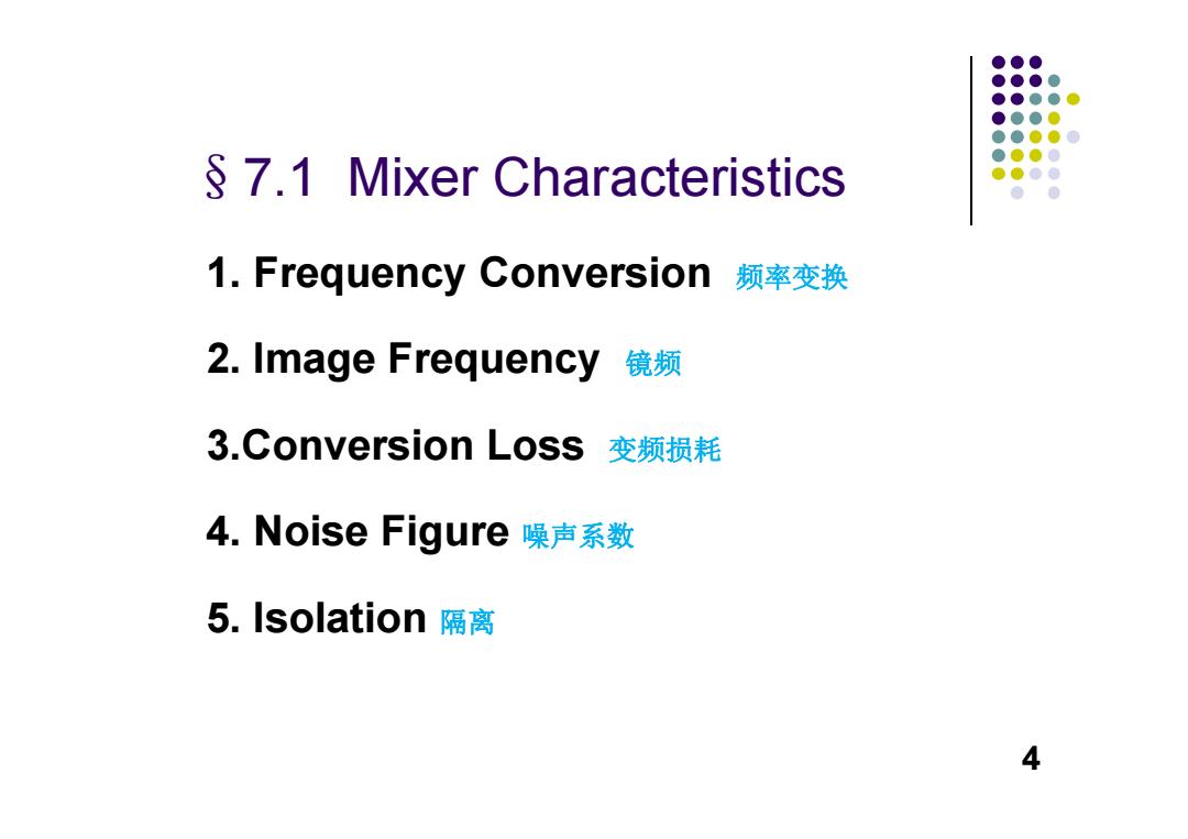
§7.1 Mixer Characteristics 1. Frequency Conversion 频率变换 2. Image Frequency 镜频 3.Conversion Loss 变频损耗 4. Noise Figure 噪声系数 5. Isolation 隔离 4

●●● ●●●● ●●●●● 1.Frequency Conversion ●●●0 ●●●●0 ●●●● ●●●● IF oscillator Mixer ● fRF=无o±fF fLo FLo-fL0Lo+亚 Signal Local oscillator Low-side band (LSB)up-side band (USB) Transmitter发射机 up-conversion上变频 Mixer fr十fr fRF fiF=fRF±无o RF oscillator RF-Lo Lo RF Lo+RF Local oscillator 2Lo-RF=IM (image frequency) Receiver接收机 down-conversion下变频 5
1. Frequency Conversion Transmitter 发射机 up-conversion 上变频 Receiver 接收机 down-conversion 下变频 5
●●● ●●●● ●●●● ●●●● 2.Image Frequency ●●●● ●●●● ●●●● For down-conversion frrl=fio+fiF,fRE2=fLo-fr They are indistinguishable at the IF stage,unless to reselect the signal and stop the noise or interference.它们在 中频没有差别,需要预先选出信号,抑制噪声或干扰, ② fio=fs±fiF noise of LO 本振的噪声 ③ f1o-fRF =fv fiu-fLo=fLo-fRE Two times mixing二次混频 fLo is the two times harmonies of LO,coming from inside or outside of mixer.f方Lo是本振的二次 谐波,来自于混频器的内外 6
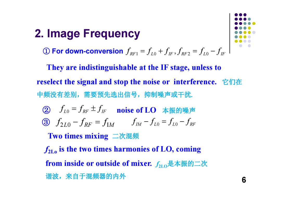
2. Image Frequency ① For down-conversion They are indistinguishable at the IF stage, unless to reselect the signal and stop the noise or interference. 它们在 中频没有差别,需要预先选出信号,抑制噪声或干扰. ② noise of LO 本振的噪声 f2Lo is the two times harmonies of LO, coming from inside or outside of mixer. f2LO是本振的二次 谐波,来自于混频器的内外 ③ Two times mixing 二次混频 10 20 , RF L IF RF L IF f f ff f f L RF IF 0 fff f20 I L RF M f f IM L L RF 0 0 ff ff 6

●●● ●●● ●●●● ●●●● 3.Conversion loss ●●●● ●●●● ●●●● PRE ● Lc=10g Pir 1 It comes from resistive losses and frequency conversion process.它来自于阻性损耗和频率变换过程 2 Diode mixers have conversion losses several dB. 二极管混频器的变频损耗是几个分贝 ③ Transistor mixers have lower conversion loss and may have conversion gain. 晶体三极管混频器变频损耗小,甚至可以获得变频增益 Minimum Lc often occurs for LO power between 5 and 13dBm,which means nonlinear analysis is required. 为了获得最小的变频损耗,本振功率在5~13dBm之间,这意味着需要 采用非线性分析
3. Conversion loss ① It comes from resistive losses and frequency conversion process.它来自于阻性损耗和频率变换过程 ② Diode mixers have conversion losses several dB. 二极管混频器的变频损耗是几个分贝 ③ Transistor mixers have lower conversion loss and may have conversion gain. 晶体三极管混频器变频损耗小,甚至可以获得变频增益 ④ Minimum L C often occurs for LO power between 5 and 13dBm, which means nonlinear analysis is required. 为了获得最小的变频损耗,本振功率在 5 ~13dBm之间,这意味着需要 采用非线性分析。 10lg RF C IF P L P 7
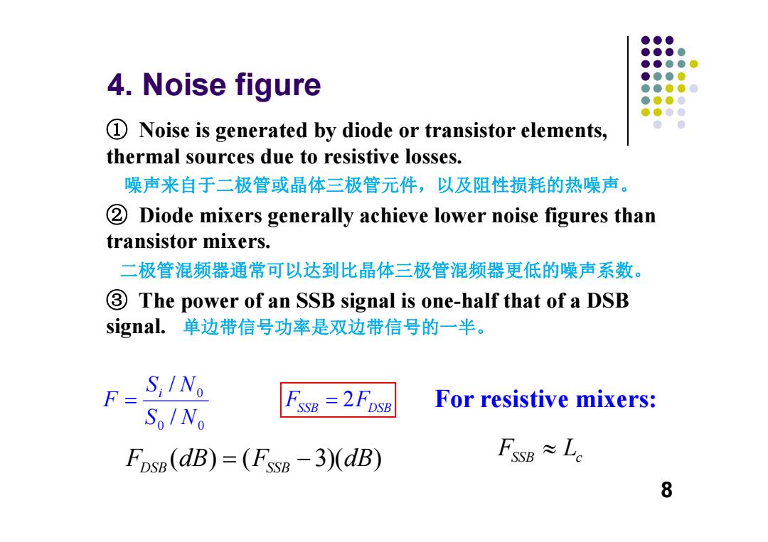
●●● ●●●● ●●●● 4.Noise figure ●●●● ●●●● ●●●● 1 Noise is generated by diode or transistor elements, ● thermal sources due to resistive losses. 噪声来自于二极管或晶体三极管元件,以及阻性损耗的热噪声。 2 Diode mixers generally achieve lower noise figures than transistor mixers. 二极管混频器通常可以达到比晶体三极管混频器更低的噪声系数。 3 The power of an SSB signal is one-half that of a DSB signal.单边带信号功率是双边带信号的一半。 S;INo For resistive mixers: SoINo FSSB =2FDSB FDSB(dB)=(FSSB-3)(dB) FssB≈Le 8
4. Noise figure ① Noise is generated by diode or transistor elements, thermal sources due to resistive losses. 噪声来自于二极管或晶体三极管元件,以及阻性损耗的热噪声。 ② Diode mixers generally achieve lower noise figures than transistor mixers. 二极管混频器通常可以达到比晶体三极管混频器更低的噪声系数。 ③ The power of an SSB signal is one-half that of a DSB signal. 单边带信号功率是双边带信号的一半。 0 0 0 / / S N S N F i 2 FSSB DSB F ( ) ( 3)( ) FDSB SSB dB F dB For resistive mixers: FSSB c L 8
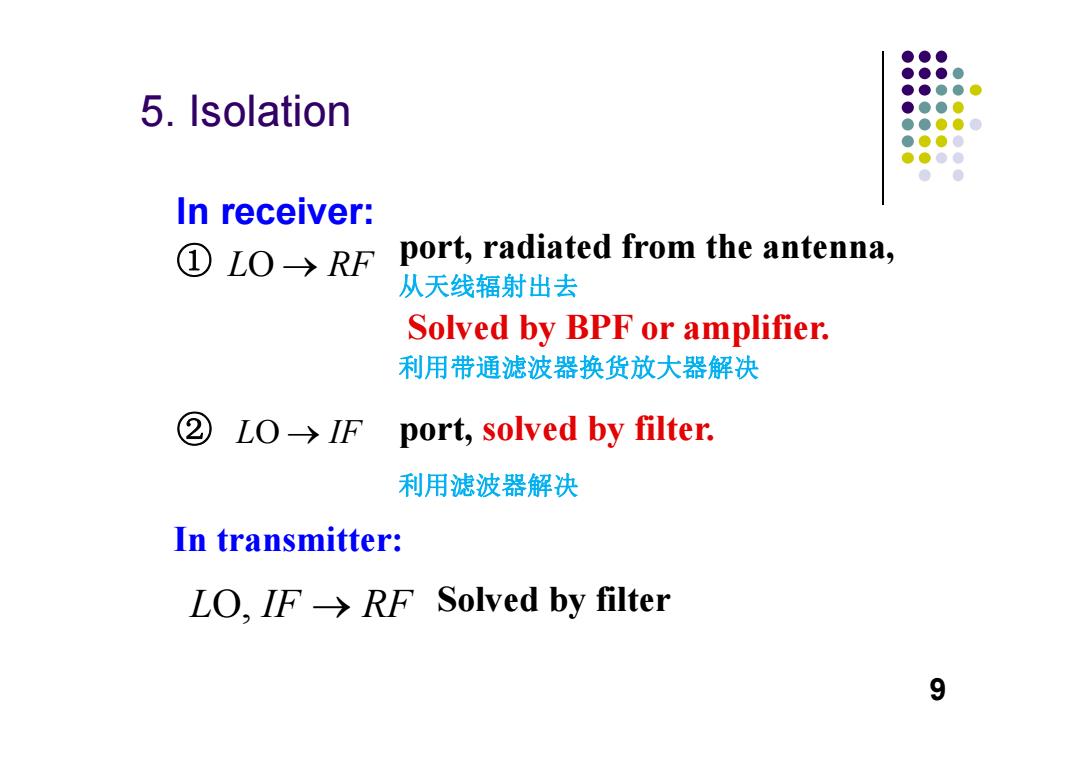
●●● ●●●● ●●●●@ 5.Isolation ●●●0 ●●●●0 ●●●● ●●●● ● In receiver: ①LO→RF port,radiated from the antenna, 从天线辐射出去 Solved by BPF or amplifier. 利用带通滤波器换货放大器解决 ② LO→IF port,solved by filter. 利用滤波器解决 In transmitter: LO.IF->RF Solved by filter 9
5. Isolation In receiver: port, radiated from the antenna, 从天线辐射出去 Solved by BPF or amplifier. 利用带通滤波器换货放大器解决 ① ② port, solved by filter. 利用滤波器解决 In transmitter: Solved by filter LO RF LO IF L IF RF O, 9
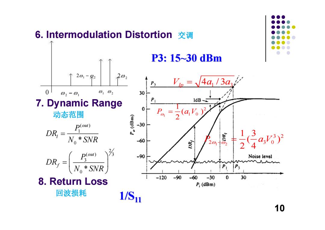
●●● ●●●● ●●●●● 6.Intermodulation Distortion交调 ●●●● ●●●● ●●●● ●●●● P3:15~30dBm 个 201-2 202 P3 VI= 4a/3a2 0 02-01 0102 30 7.Dynamic Range P 动态范围 )(a%2 DR P(ou) -30 13 No*SNR 60 2014 2 a)2 DB, p(ou) -90 Noise level MM N SNR 8.Return Loss -120-90 60 -30 0 30 P(dBm) 回波损耗 1/S1n 10
7. Dynamic Range 动态范围 6. Intermodulation Distortion 交调 P3: 15~30 dBm 2 1 1 2 2 1 2 2 1 2 0 1 2 1 0 1 ( ) 2 P aV 1 2 3 2 2 30 1 3( ) 2 4 P a V V aa Ip 4 /3 1 3 8. Return Loss 回波损耗 1/S11 ( ) 1 0 2 ( ) 3 3 0 * * out l out f P DR N SNR P DR N SNR 10