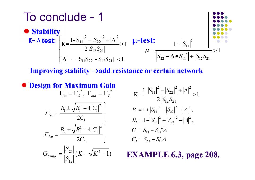
To conclude 1 ●●● ●●●● ●●●●● ●●●0 ●t Stability ●●●●0 ●.●●● K-△test: k-1小smf-szP+1μ-test: 1-Saf 2S12S21 A=ISuS22 S12S21 add resistance or certain network Design for Maximum Gain 「m=「s',「om=rL K=1-n- 2S12S21 B±VB-4C B=1+lS2-lS22-42, 2C B2=1-lSP+lS22-4, r.=8±y-4G C1=S1-S24 2C2 C2=S22-S14 EXAMPLE 6.3,page 208
To conclude - 1 Stability K-Δtest: -test: Improving stability add resistance or certain network Design for Maximum Gain 2 22 11 22 12 21 11 22 12 21 1- S K= >1 2 |S S - S S | 1 S S S 2 11* 22 11 12 21 1 1 S S S SS * * , in S out L 21 2 max 12 ( 1) T S G KK S 2 22 11 22 12 21 1- S K= >1 2 S S S 2 2 11 1 1 2 2 22 2 2 4 2 4 2 Sm Lm BB C C BBC C 2 22 1 11 22 2 22 2 11 22 1 11 22 2 22 11 1 , 1 , B SS B SS CS S CS S EXAMPLE 6.3, page 208
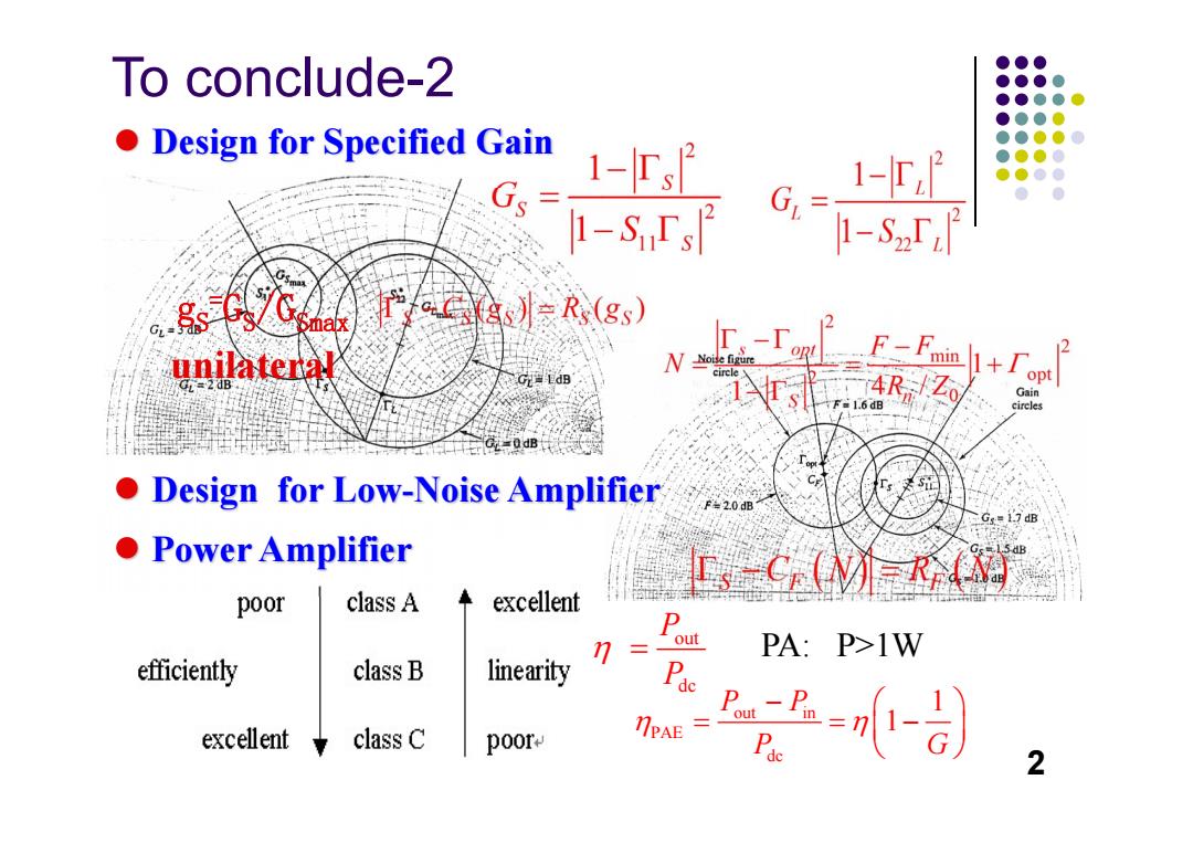
To conclude-2 ●●● ●●●● ●●●●● ●●●● Design for Specified Gain ●●●● 1-rs2 ●●●● G 1-r8 ●●● 1-S「2 1-Sz「i focas)Rs(gs) unilateral E.-「 F-Fmin 1+1 4R/Zo opt Gain ireles Design for Low-Noise Amplifier 20 .7 dB ●Power Amplifier I-CMRN poor class A excellent PA:P>1W efficiently class B linearity excellent class C poor 2
2 gS=GS/GSmax unilateral Design for Specified Gain Design for Low-Noise Amplifier out PA: P>1W dc P P out in PAE dc 1 1 P P P G To conclude-2 Power Amplifier
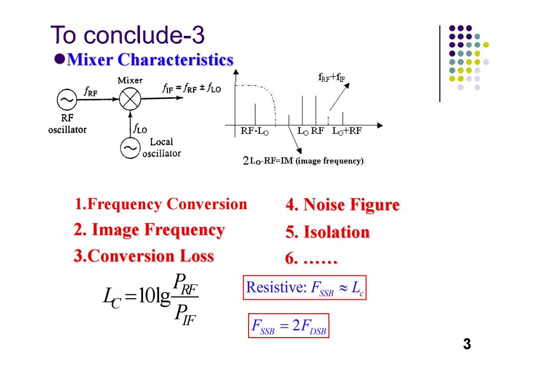
To conclude-3 ●●● ●●●● ●●●●● OMixer Characteristics ●●●0 ●●●●0 ●●●● Mixer fRr十fr ●●●● fRF fF=fRF±f九o ● ● RF oscillator 无o RF-Lo Lo RF LO+RF Local oscillator 2Lo-RF=IM (image frequency) 1.Frequency Conversion 4.Noise Figure 2.Image Frequency 5.Isolation 3.Conversion Loss 6.… ,P哑 Icz10I PE Resistive:Fsw≈L. FssB =2FDSB 3
To conclude-3 Mixer Characteristics 1.Frequency Conversion 2. Image Frequency 3.Conversion Loss 6. …… 3 4. Noise Figure 5. Isolation 10lg RF C IF P L P
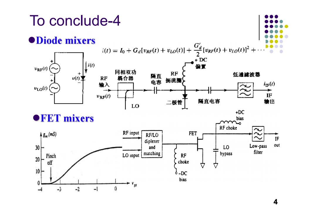
To conclude-4 ●●● ●●●● ●●●●● ●●●0 ●Diode mixers ●●●●0 ●.●●0 i(t)=1o+GalvRF(t)+vLo(t)+ C4[wr)+woP+ ●●●● ●● DC i(t) VRF(r) 偏量 同相双功 RF 糊合器 隔直 RF 低通滤波器 电容 扼流圈 ir(t) vLO(D) 输入 VRF(t) 正 二极管 隔直电容 镶出 LO +DC OFET mixers bias n RF choke 8(mS) RFinput RF/LO FET diplexer IF 30F and LO Low-pass o matching filter 20 Pinch LO input RF bypass off choke 10 6-DC bias 0 -4 -2 0 4
To conclude-4 Diode mixers FET mixers 4
To conclude-5 122. ④ 高频旁路 fs→ 以☑ Z Z 中频 接地 卤 K-■ ② ③ 丝变阻器 D2 Z/2 Single Balanced 4 Single-Ended ③ 宁 (t) LO/In i(t) D2 RF/In IF/Out Single Balanced (mm-wave) 5
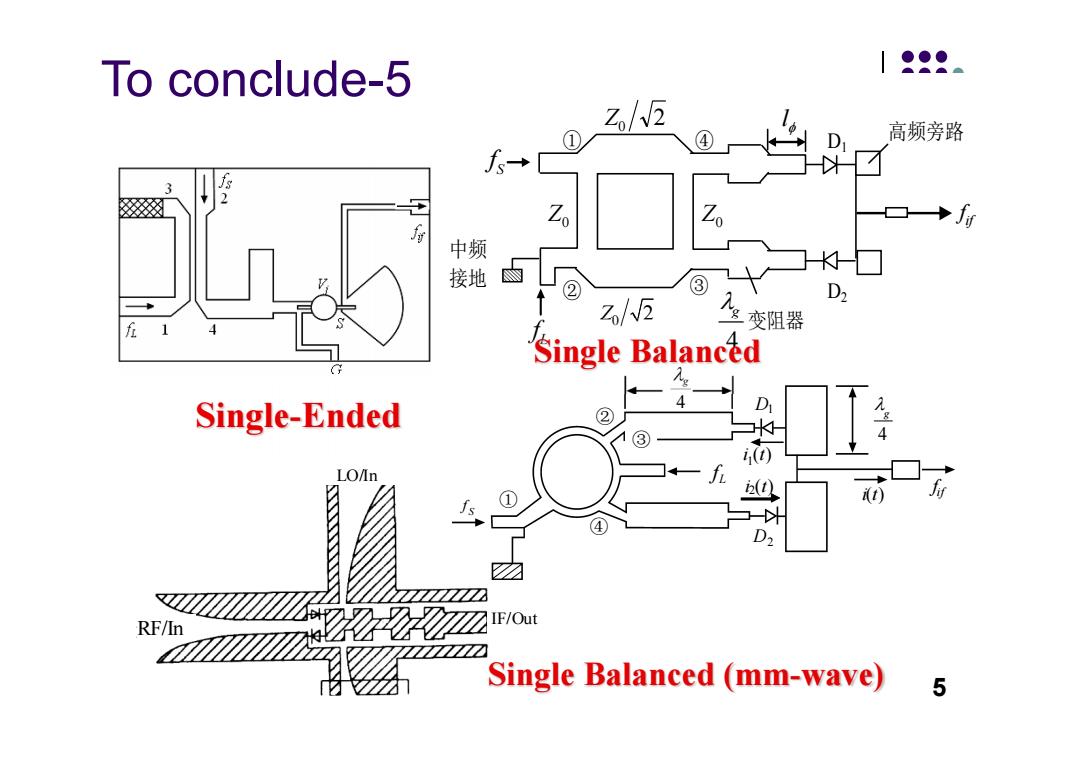
RF/In IF/Out LO/In 5 ② ③ ① ④ 高频旁路 中频 接地 Lf Z0 D1 D2 Z0 4 g 变阻器 Z0 2 Sf l 0 Z 2 if f Single-Ended Sf ① ② ④ ③ i1(t) i2(t) D2 D1 4 g i(t) if f Lf 4 g To conclude-5 Single Balanced Single Balanced (mm-wave)
●●● Microwave and RF ●●●● ●●● ●●0 ●●● ●●● Design of Wireless ●●00 ● Systems Chapter 8 Transistor Oscillators And Frequency Synthesizers Dr.Xian Qi Lin 7
Microwave and RF Design of Wireless Systems Transistor Oscillators And Frequency Synthesizers Chapter 8 Dr. Xian Qi Lin 7

●●● ●●●● ●●●心 ●●●● Functions:Proving precisely controlled sources for ●●●●0 ●●●● frequency conversion and carrier generation. ●●●● ●● Simple transistor oscillator:lack the frequency stability and low-noise performance.简单的晶体管振荡器频率稳定度 和低噪声性能差。 Require: Frequency stability:0.5~2 PPM PPM:10-6△f/f;(PPb:10-9:PPt:10-12) Phase noise:-80~-110dBc/Hz @10kHz Crystal controlled oscillators with high frequency stability and low phase noise are often used to provide accurate frequency reference.晶体控制的振荡器具有高的频率稳 定度和低的相位噪声,因而常常用来提供精确的频率参考 8
Functions: Proving precisely controlled sources for frequency conversion and carrier generation. Simple transistor oscillator: lack the frequency stability and low-noise performance.简单的晶体管振荡器频率稳定度 和低噪声性能差。 Frequency stability: 0.5~2 PPM PPM: 10-6Δf/f; (PPb: 10-9; PPt: 10-12) Phase noise:-80~-110dBc/Hz @10kHz Require: Crystal controlled oscillators with high frequency stability and low phase noise are often used to provide accurate frequency reference.晶体控制的振荡器具有高的频率稳 定度和低的相位噪声,因而常常用来提供精确的频率参考 8
●●● ●●●● ●●●●● ●●●0 ●●●●0 ●●●● ●●●● ●● §8.1 RF Oscillators射频振荡器 §8.2 Microwave Oscillators微波振荡器 8.3 Frequency Synthesis Methods 频率合成方法 8.5 Oscillator Phase Noise 振荡器相位噪声 9
§8.1 RF Oscillators射频振荡器 §8.2 Microwave Oscillators微波振荡器 §8.3 Frequency Synthesis Methods 频率合成方法 §8.5 Oscillator Phase Noise 振荡器相位噪声 9
●●● ●●●● ●●●●● §8.1 RF Oscillators ●●●● ●●●●0 ●●●● ●●●● Oscillator is a nonlinear circuit that converts DC ●● power to an AC waveform providing sinusoidal output in wireless systems.振荡器是一个非线性电路,它把 直流的功率变成交流,并且在无线系统中提供正弦输出 Vi(@) Vo(w) Vo(@)=AV;(@)+H(@)AV(@) A 、',(o) H(@) Vo(@)=]-AH(@) If 1-AH(@)=0,when Vi(@)=0,Vo (@)t0,oscillate. The frequency of oscillator depends on the network H(@). 振荡器的频率依赖于网络的传输函数 10
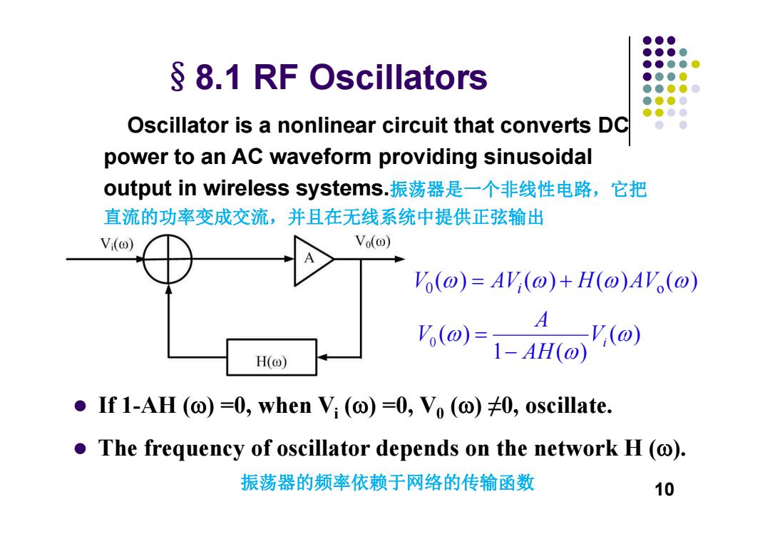
§8.1 RF Oscillators Oscillator is a nonlinear circuit that converts DC power to an AC waveform providing sinusoidal output in wireless systems.振荡器是一个非线性电路,它把 直流的功率变成交流,并且在无线系统中提供正弦输出 If 1-AH () =0, when Vi () =0, V0 () ≠0, oscillate. The frequency of oscillator depends on the network H (). 振荡器的频率依赖于网络的传输函数 ( ) 1 ( ) ( ) 0 Vi AHA V 0 o () () () () V AV H AV i 10
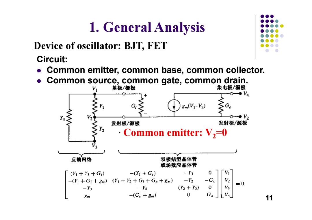
●●● ●●●● 1.General Analysis ●●●●● ●●●0 ●●●●0 ●●●0 Device of oscillator:BJT,FET ●●●● Circuit: Common emitter,common base,common collector. ● Common source,common gate,common drain. 基极/摄极 集电极/漏极 SY G 8m(Y-V2) 0◆V2 发射极/源极 发射极/源极 ·Common emitter:V2=0 反馈网络 双极结型晶体普 或场效应晶体管 「(Y1+Y3+G) -(Y十G) -Y3 0 7 -(Y1 +Gi+gm)(Y1+Y2+Gi+Go+8m) -Y2 -Go =0 -Y3 -Y2 (Y2+Y) 0 8m -(G。+gm) 0 Go 11
Common emitter: V2=0 1. General Analysis Circuit: Common emitter, common base, common collector. Common source, common gate, common drain. Device of oscillator: BJT, FET 11