●●】 ●●●● ●●●●● ●●● 1●●● Microwave and RF Design of Wireless Systems Chapter 5 Filter Dr.Xian Qi Lin 1
Microwave and RF Design of Wireless Systems Chapter 5 Filter Dr. Xian Qi Lin 1
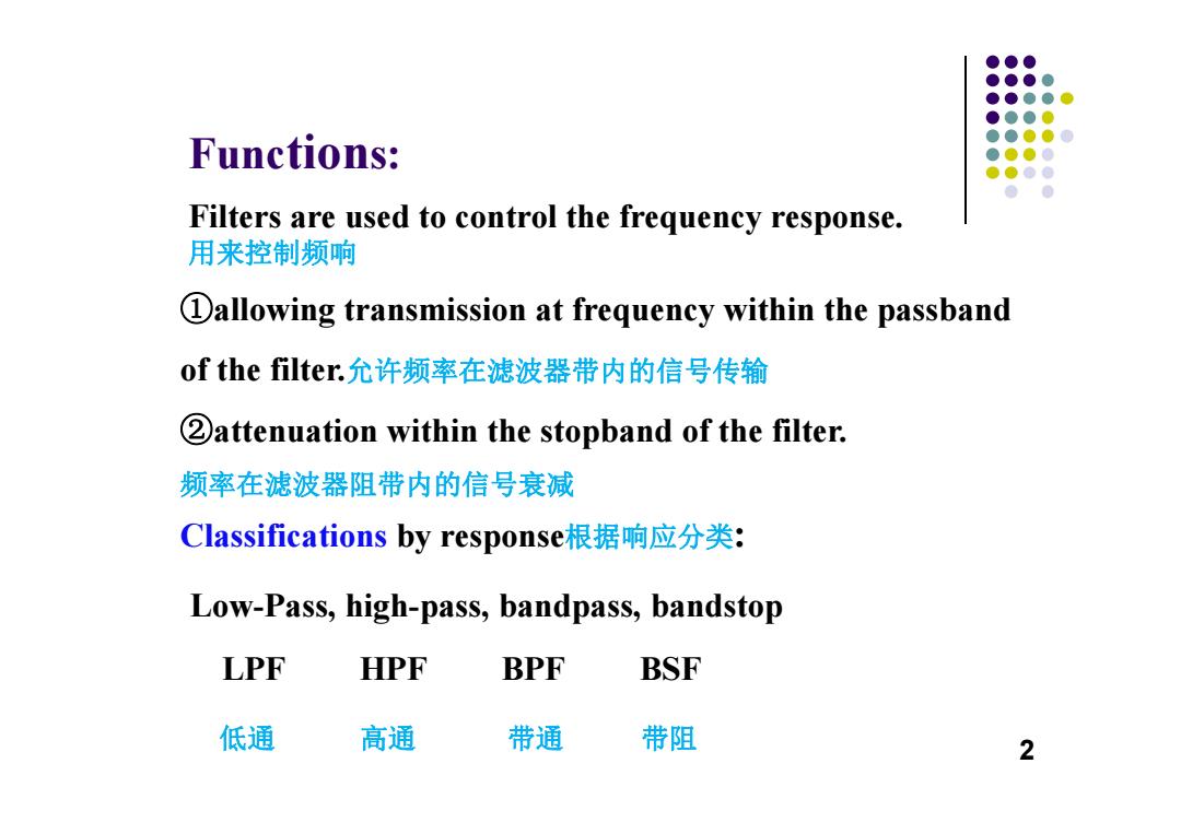
●●● ●●●● ●●●● ●●●● ●●●●0 Functions: ●●●● ●●●● ● ● Filters are used to control the frequency response. 用来控制频响 Dallowing transmission at frequency within the passband of the filter.允许频率在滤波器带内的信号传输 2attenuation within the stopband of the filter. 频率在滤波器阻带内的信号衰减 Classifications by response根据响应分类: Low-Pass,high-pass,bandpass,bandstop LPF HPF BPF BSF 低通 高通 带通 带阻 2
Filters are used to control the frequency response. 用来控制频响 Functions: ①allowing transmission at frequency within the passband of the filter.允许频率在滤波器带内的信号传输 ②attenuation within the stopband of the filter. 频率在滤波器阻带内的信号衰减 Classifications by response根据响应分类 : Low-Pass, high-pass, bandpass, bandstop LPF HPF BPF BSF 低通 高通 带通 带阻 2
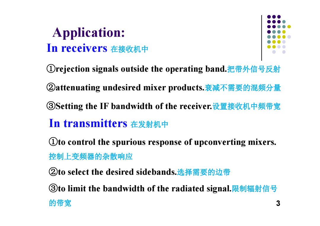
●●● ●●●● ●●●● Application: ●●●● ●●●● ●●●● n receivers在接收机中 ●●●● ①rejection signals outside the operating band.把带外信号反射 ②attenuating undesired mixer products..衰减不需要的混频分量 ③Setting the IF bandwidth of the receiver.设置接收机中频带宽 In transmitters在发射机中 Dto control the spurious response of upconverting mixers. 控制上变频器的杂散响应 ②to select the desired sidebands..选择需要的边带 ③to limit the bandwidth of the radiated signal.限制辐射信号 的带宽 3
Application: In receivers 在接收机中 ①rejection signals outside the operating band.把带外信号反射 ②attenuating undesired mixer products.衰减不需要的混频分量 ③Setting the IF bandwidth of the receiver.设置接收机中频带宽 In transmitters 在发射机中 ①to control the spurious response of upconverting mixers. 控制上变频器的杂散响应 ②to select the desired sidebands.选择需要的边带 ③to limit the bandwidth of the radiated signal.限制辐射信号 的带宽 3
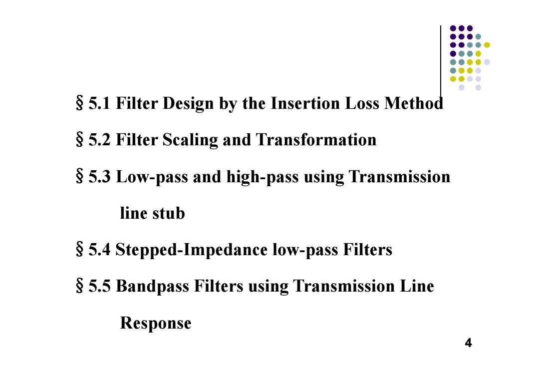
●●● ●●●● ●●●●● ●●●0 ●●●●0 ●●●● ●●●● ●● S 5.1 Filter Design by the Insertion Loss Method 5.2 Filter Scaling and Transformation 5.3 Low-pass and high-pass using Transmission line stub 5.4 Stepped-Impedance low-pass Filters 5.5 Bandpass Filters using Transmission Line Response 4
§5.1 Filter Design by the Insertion Loss Method §5.2 Filter Scaling and Transformation §5.3 Low-pass and high-pass using Transmission line stub §5.4 Stepped-Impedance low-pass Filters §5.5 Bandpass Filters using Transmission Line Response 4
●●● ●●● 5.1 Filter Design by the Insertion ●●●● ●●●● ●●●● Loss Method ●●●● ●●● Ideal filters have √Zero insertion loss in the passband;通带内零插损 √Infinite attenuation in the stopband;阻带内衰减无限大 √Linear phase response in the passband,.通带内相位线性 Compromises must be made. The insertion loss method allow a high degree of control over the passband and stopband amplitude and phase characteristics. 插入损耗法能够方便地控制带内和带外的幅度和相位 1.Characterization by Power Loss Ratio 2.Maximally Flat Low-pass Filter prototype. 3.Equal-Ripple Low-pass Filter prototype. 5
§5.1 Filter Design by the Insertion Loss Method Ideal filters have Zero insertion loss in the passband;通带内零插损 Infinite attenuation in the stopband ;阻带内衰减无限大 Linear phase response in the passband.通带内相位线性 Compromises must be made. The insertion loss method allow a high degree of control over the passband and stopband amplitude and phase characteristics. 插入损耗法能够方便地控制带内和带外的幅度和相位 1. Characterization by Power Loss Ratio 2. Maximally Flat Low–pass Filter prototype. 3. Equal–Ripple Low–pass Filter prototype. 5
●●● ●●●● ●●●●心 ●●●● 1.Characterization by Power Loss Ratio ●●●● ●●●● ●●●● ●● Power Loss ratio:P 1-r(o IL(dB)=101g PLR Because of the causal properties of networks由于网s络的 因果关系,T(o)2 is an even function偶函数ofo(see Problem 5.1), Therefore,writing|T(o)l2 as a polynomial多项式ino2 of-i两 M(o2) M(O) PR=1+ N(o2) 6
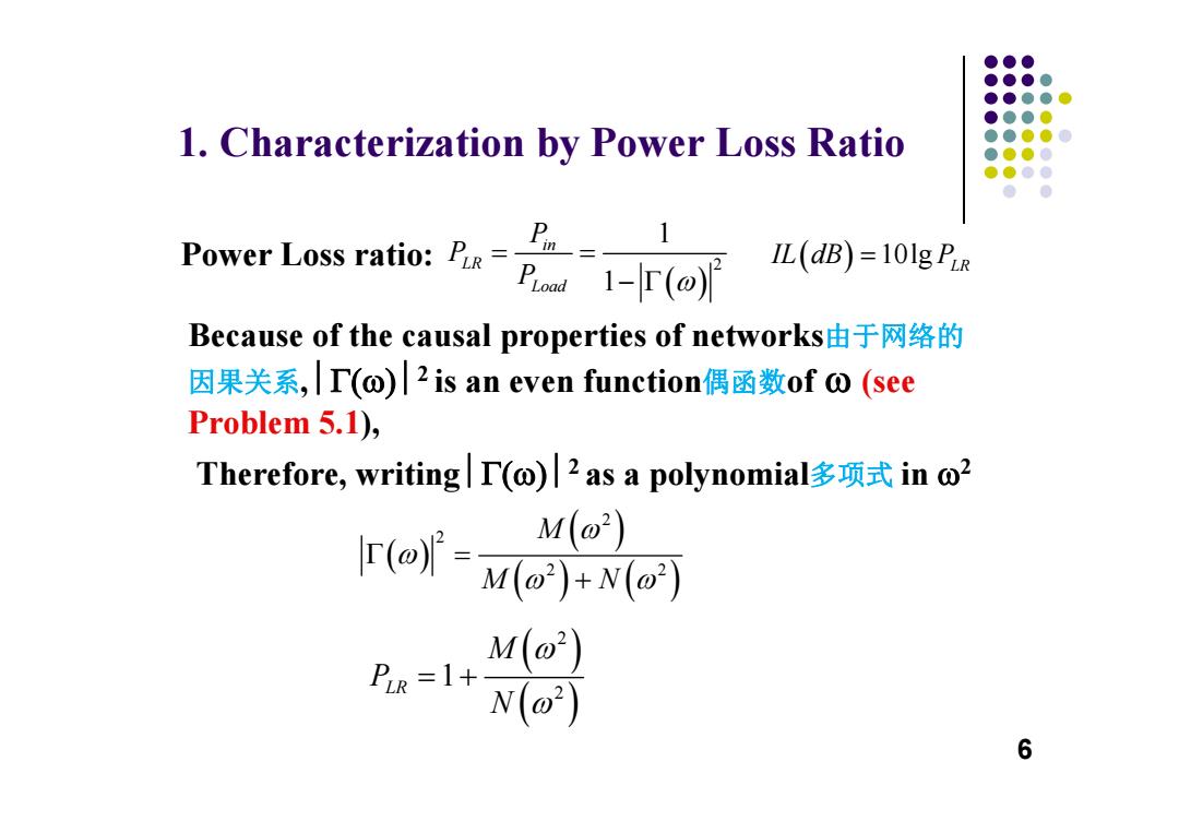
1. Characterization by Power Loss Ratio Power Loss ratio: Because of the causal properties of networks由于网络的 因果关系, 2 is an even function偶函数of (see Problem 5.1), Therefore, writing 2 as a polynomial多项式 in 2 6 2 1 1 in LR Load P P P 10lg L R IL dB P 2 2 2 2 M M N 2 2 1 LR M P N
●●● ●●●● ●●●●心 ●●●0 Maximally flat response (Butterworth) ●●●● ●●●● ●●●● ●● where N is the order of the filter 2N PLR =1+k2 滤波器的阶数 @is the cutoff frequency截止频率 Passband::o=0~o。 The power loss ratio at the band edge @c: PIR=1+k2 IF k=1,then PLR=3dB 2N FOr0>0。PR≈k2 0 7
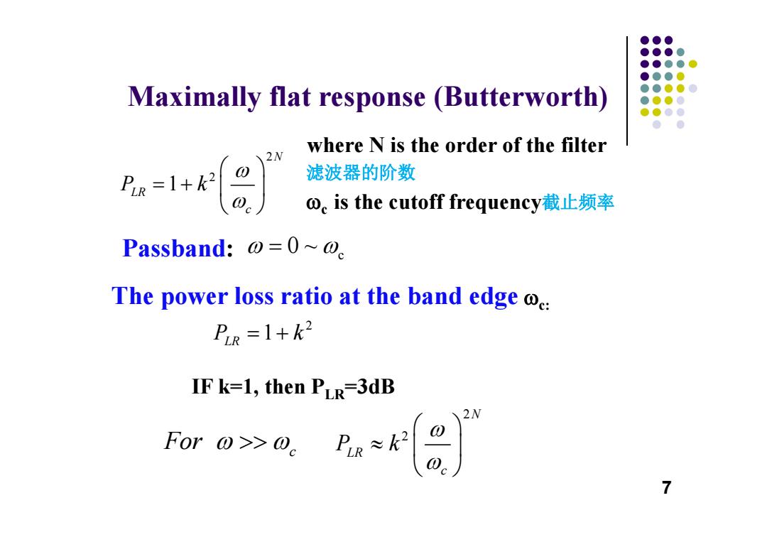
Maximally flat response (Butterworth) where N is the order of the filter 滤波器的阶数 c is the cutoff frequency截止频率 Passband: The power loss ratio at the band edge c: IF k=1, then PLR=3dB 7 2 2 1 N LR c P k c 0 ~ 2 1 P k LR For c 2 2 N LR c P k
●●● Equal-ripple response (Chebyshev) ●●●● ●●●●● ●●●0 PLR ●●●●0 ●●●0 ●●●● Equal ● ripple Maximally flat +2 0.5 1.0 1.5 PiR=1+k2T Where T(x)is a Chebyshev polynomical of order N. 阶数为N的切比雪夫多项式 The ripple of amplitude in the pass band is 1+k2. w0.g2r2,c.2) 2N 8
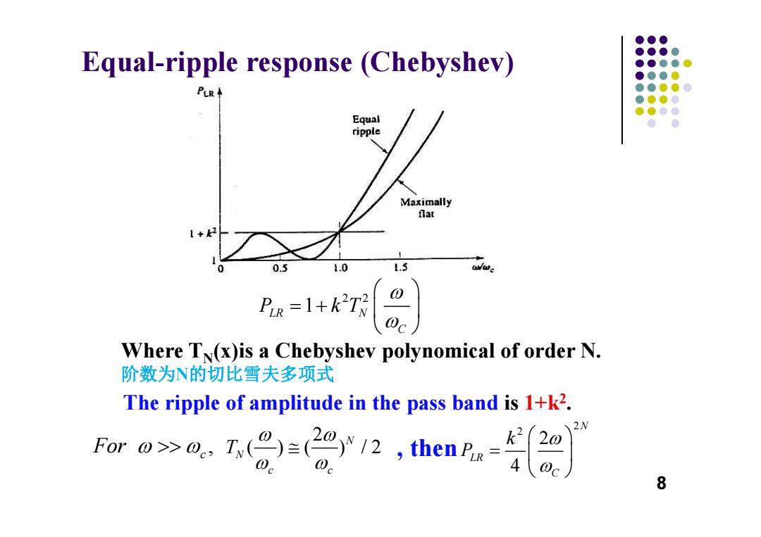
Equal-ripple response (Chebyshev) Where T N(x)is a Chebyshev polynomical of order N. 阶数为 N的切比雪夫多项式 The ripple of amplitude in the pass band is 1+k 2. , then 8 2 2 1 LR N C P kT , For c 2 ( ) ( ) /2 N N c c T 2 2 2 4 N LR C k P
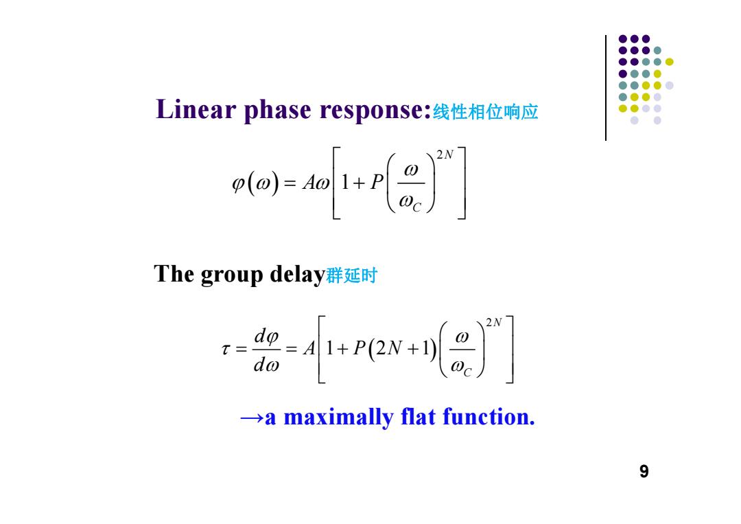
●●● ●●●● ●●●●● ●●●0 ●●●●0 ●●●0 Linear phase response:线性相位响应 ●●●● ● o创al+r川 The group delay群延时 0ex+n8 a maximally flat function. 9
Linear phase response:线性相位响应 The group delay群延时 →a maximally flat function. 9 2 1 N C A P 2 1 21 N C d A PN d
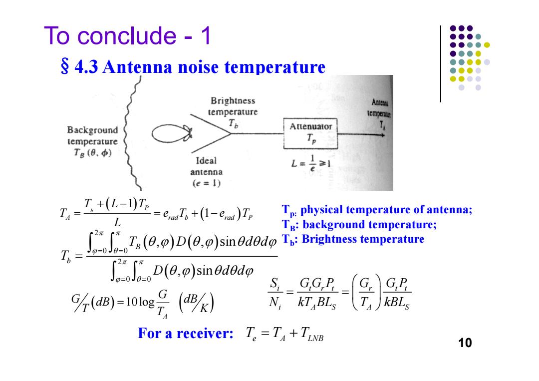
To conclude-1 ●●● ●●●● ●●●●● ●●●0 S 4.3 Antenna noise temperature ●●●● ●●●0 ●●● ● ● Brightness Anteen temperature tempenta Background To Attenuator temperature Tp Tg (0.) Ideal antenna L=刘 (e=I) T +(L-1)Tp T4= =emTs+(1-eu)Tr Tp:physical temperature of antenna; L TB:background temperature; Th= ()sinOdod temprature )sin0d0dp J0=0 GP 9%=10ε号(9 N,kT BLs kBLs For a receiver:T=T+TLNE 10
To conclude - 1 §4.3 Antenna noise temperature Tp: physical temperature of antenna; TB: background temperature; Tb: Brightness temperature For a receiver: 10 1 1 b P A rad b rad P TLT T eT e T L 2 0 0 2 0 0 , , sin , sin B b T D dd T D dd 10log A G G dB dB T K T i t rt tt r i AS A S S GG P GP G N kT BL T kBL TTT e A LNB