
第4卷第6期 智能系统学报 Vol.4 No.6 2009年12月 CAAI Transactions on Intelligent Systems Dec.2009 doi:10.3969/j.issn.16734785.2009.06.014 Optimal coordination of directional over current relays using evolutionary programming M.Geethanjali,S.Mary Raja Slochanal (Department of Electrical and Electronics Engineering,Thiagarajar College of Engineering,Madurai-625015,India) Abstract:Co-ordination of directional over current relays (DOCR)requires the selection and setting of relays so as to se- quentially isolate only that portion of the power system where an abnormality has occurred.The problem of coordinating protective relays in electrical power systems consists of selecting suitable settings such that their fundamental protective function is met,given operational requirements of sensitivity,selectivity,reliability and speed.Directional over current relays are best suited for protection of an interconnected sub-station transmission system.One of the major problems asso- ciated with this type of protection is the difficulty in coordinating relays.To insure proper coordination,all the main/back up relay pairs must be determined.This paper presents an effective algorithm to determine the minimum number of break points and main/back up relay pairs using relative sequence matrix(RSM).A novel optimization technique based on ev- olutionary programming was developed using these main back up relay pairs for directional over current relay coordination in multi-loop networks.Since the problem has multi-optimum points,conventional mathematics based optimization tech- niques may sometimes fail.Hence evolutionary programming (EP)was used,as it is a stochastic multi-point search opti- mization algorithm capable of escaping from the local optimum problem,giving a better chance of reaching a global opti- mum.The method developed was tested on an existing 6 bus,7 line system and better results were obtained than with conventional methods. Keywords:power system protection;protection coordination;directional over current relay;evolution- ary programming;optimization technique CLC Number:TP18 Document code:A Article ID:1673-4785(2009)06-0549-12 The main function of power system protection is to Since it is very difficult to find a proper relay setting isolate only the faulty component or a minimal set of to meet the requirements by traditional methods,partial components as soon as the fault occurs.Since the main optimization of OC relay settings based on predetermined protection system may sometimes fail(relay fault or pick-up current settings were developedis6.Since they breaker fault),there must be back up either in the cannot take all system conditions into consideration the same station (local back up)or in neighboring lines results may get trapped at local optimum relay settings. (remote back up)with time delay according to the se-Therefore some of the different multi-point search algo- lectivity requirement.The determination of the time rithms such as genctic algorithms and evolutionary delays of all the back up relays,in the main/back up programming (EP)are used to reach global optimum in relay pairs,is known as coordination of the protection a better way.Thus recently the problem of coordinating system.Generally,in meshed networks with multiple DOCR in power systems was stated and solved in the generation buses,directional protection relays are framework of optimization theory.For this paper,a used.Among those,directional over current relays novel approach using EP for optimal coordination of (DOCR)are the major protection devices in distribu- DOCR was developed.The work done involved the fol- tion systems.The major problems associated with lowing two stages: DOCR are relay setting calculations and coordination. 1)Determination of a minimum set of break points Received Date:2008-11-24. and the main/back up relay pairs using relative se- Corresponding Author:M.Geethanjali.E-mail:mgeee@tce.edu. quence matrix (RSM)

·550. 智能系统学报 第4卷 2)Development of a DOCR coordination algorithm dal method.But in these methods the solution obtained based on EP using the main/back up relay pairs deter- may not be taken as a global optima because there is a mined in 1). chance of getting trapped in local optima.Hence in Thus an effective "optimal"solution to the co- this proposed method EP which gives global optima is ordination problem was obtained. used to optimize the problem. 1 DOCR coordination 2 Development of optimal DOCR co- Directional over current relays are best suited for ordination algorithm protection of interconnected sub-system transmission systems or as secondary protection of main transmission The method developed for optimal co-ordination of systems.Co-ordination of these protective relays in- directional over current relays consists of the following volves their selection and setting so as to sequentially i- steps: solate only that portion of the power system where the 2.1 Determination of main/back up relay pairs abnormality occurs.To achieve this isolation,it is nec- The relay which clears the fault in the protected essary to set protective devices so that only the device section as quickly as possible is called the main relay. nearest to the fault opens and isolates the faulty circuit The relay which operates after a slight time delay,if from the system.The problem of coordinating protec- the main relay does not operate to trip its circuit break- tive relays in electrical power systems consists of selec- er,is known as the back up relay.In order to obtain ting suitable settings such that their fundamental pro- proper co-ordination,it is very important to find all the tective function is met given requirements of sensitivi- main-back up relay pairs.Each main-back up relay ty,selectivity,reliability and speed.The setting of pair is set according to the coordination interval.All DOCRs has to satisfy all possible network configura- main-back up relay pairs are found using break points tions subject to type and location of all possible faults. and a relative sequence matrixs,10 Back up protective devices are set to operate at 1)Determination of break points. some predetermined time interval after the primary de- The starting points of sequences that ensure coor- vices fails to operate.When remote back up protection is dination are called break points.Determination of break required,then coordination should be done for all possi- points(BPs)yields the minimum set of relays to start ble main/back up relay pairs at corresponding stations. the co-ordination process.They are determined using a Since the relays are directional ones,the mesh should run simple loop matrix (L)which is determined by using in both directions to include all of the relays.It is neces- the network topology. sary to determine a set of starting relays which would The simple loop matrix L is determined using the break all the meshes of the network when they are simul- following steps: taneously open.Those relays are known as"Break Points" DFormation of network graph,edges and verti- (BPs)tio」 ces:A network graph is obtained from the network by Conventionally,the co-ordination of directional o- replacing the nodes with vertices and the lines with the ver current relays (DOCR)is done using interactive edges of the network.The edges are numbered from 1 methods,wherein the co-ordination engineer runs dif-to e and vertices from 1 to v. ferent cases for distinct faults and configurations,until 2Numbering of relays:The relays are numbered an acceptable solution is reached.Unfortunately the in the correct manner.For example,if the relay on solution found by these procedures is not optimal in any line"i"is located at the initial vertex of the edge, strict sense,but simply the best of the possible solu- and is numbered as "i"then the relay at the final tions tried [s6.Later,optimality was obtained using vertex of the edge is numbered as e+i. conventional optimization methods like the Gauss-Sei- 3Formation of sub matrix F:Any circuit of the
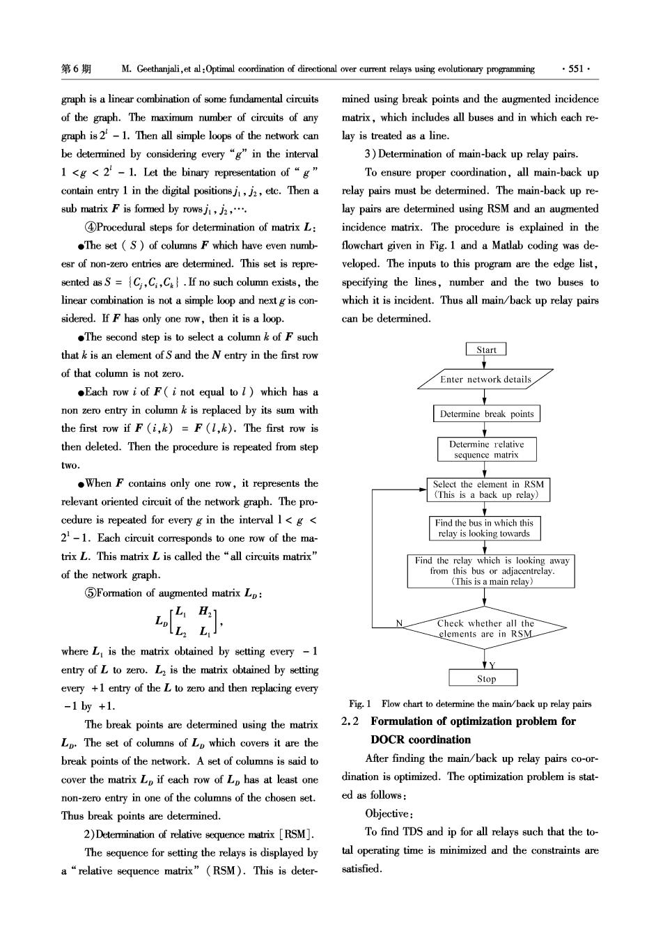
第6期 M.Geethanjali,et al:Optimal coordination of directional over current relays using evolutionary programming ·551· graph is a linear combination of some fundamental circuits mined using break points and the augmented incidence of the graph.The maximum number of circuits of any matrix,which includes all buses and in which each re- graph is2-1.Then all simple loops of the network can lay is treated as a line. be determined by considering every "g"in the interval 3)Determination of main-back up relay pairs. 1 <g<2-1.Let the binary representation of "g" To ensure proper coordination,all main-back up contain entry 1 in the digital positionsj,j2,etc.Then a relay pairs must be determined.The main-back up re- sub matrix F is formed by rowsj,j,. lay pairs are determined using RSM and an augmented 4Procedural steps for determination of matrix L: incidence matrix.The procedure is explained in the .The set (S)of columns F which have even numb- flowchart given in Fig.1 and a Matlab coding was de- esr of non-zero entries are determined.This set is repre- veloped.The inputs to this program are the edge list, sented as S=C,C:,C..If no such column exists,the specifying the lines,number and the two buses to linear combination is not a simple loop and next g is con- which it is incident.Thus all main/back up relay pairs sidered.If F has only one row,then it is a loop. can be determined. The second step is to select a column k of F such that k is an element ofS and the N entry in the first row Start of that column is not zero. Enter network details .Each row i of F(i not equal to l)which has a non zero entry in column k is replaced by its sum with Determine break points the first row if F(i,k)=F (,k).The first row is then deleted.Then the procedure is repeated from step Determine relative sequence matrix two. .When F contains only one row,it represents the Select the element in RSM relevant oriented circuit of the network graph.The pro- (This is a back up relay) cedure is repeated for every g in the interval I<g< Find the bus in which this 21-1.Each circuit corresponds to one row of the ma- relay is looking towards trix L.This matrix L is called the "all circuits matrix" Find the relay which is looking away of the network graph. from this bus or adjacentrelay. (This is a main relay.〉 5Formation of augmented matrix Lp: 吃1 Check whether all the elements are in RSM where L is the matrix obtained by setting every -1 entry of L to zero.L2 is the matrix obtained by setting Y Stop every +1 entry of the L to zero and then replacing every -1by+1. Fig.1 Flow chart to determine the main/back up relay pairs The break points are determined using the matrix 2.2 Formulation of optimization problem for Lp.The set of columns of Lp which covers it are the DOCR coordination break points of the network.A set of columns is said to After finding the main/back up relay pairs co-or- cover the matrix Lp if each row of Lp has at least one dination is optimized.The optimization problem is stat- non-zero entry in one of the columns of the chosen set. ed as follows: Thus break points are determined. Objective: 2)Determination of relative sequence matrix [RSM]. To find TDS and ip for all relays such that the to- The sequence for setting the relays is displayed by tal operating time is minimized and the constraints are a“relative sequence matrix”(RSM).This is deter- satisfied
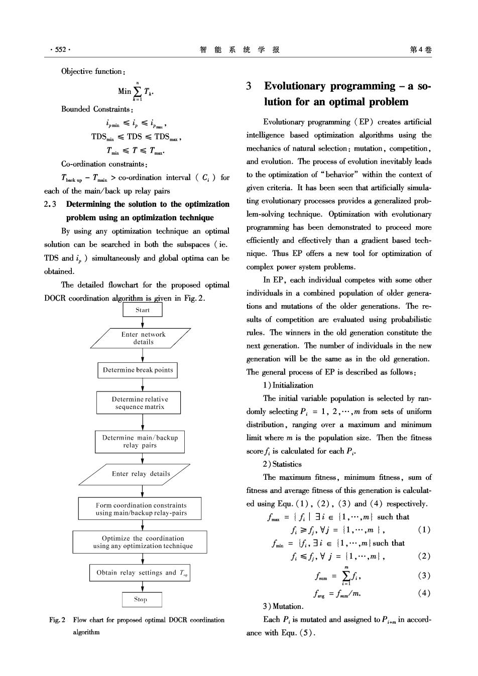
.552. 智能系统学报 第4卷 Objective function: Min∑I. 3 Evolutionary programming-a so- 自 lution for an optimal problem Bounded Constraints: ip血≤in≤in’ Evolutionary programming (EP)creates artificial TDSin≤TDS≤TDS, intelligence based optimization algorithms using the Taia≤T≤Tnm mechanics of natural selection:mutation,competition, Co-ordination constraints: and evolution.The process of evolution inevitably leads Thackp-Tm>co-ordination interval (C)for to the optimization of "behavior"within the context of each of the main/back up relay pairs given criteria.It has been seen that artificially simula- 2.3 Determining the solution to the optimization ting evolutionary processes provides a generalized prob- problem using an optimization technique lem-solving technique.Optimization with evolutionary By using any optimization technique an optimal programming has been demonstrated to proceed more solution can be searched in both the subspaces(ie. efficiently and effectively than a gradient based tech- TDS and i,)simultaneously and global optima can be nique.Thus EP offers a new tool for optimization of obtained. complex power system problems. The detailed flowchart for the proposed optimal In EP,each individual competes with some other DOCR coordination algorithm is given in Fig.2. individuals in a combined population of older genera- Start tions and mutations of the older generations.The re- sults of competition are evaluated using probabilistic Enter network rules.The winners in the old generation constitute the details next generation.The number of individuals in the new generation will be the same as in the old generation. Determine break points The general process of EP is described as follows: 1)Initialization Determine relative The initial variable population is selected by ran- sequence matrix domly selecting P:=1,2,..,m from sets of uniform distribution,ranging over a maximum and minimum Determine main/backup limit where m is the population size.Then the fitess relay pairs scoref:is calculated for each P:. 2)Statistics Enter relay details The maximum fitness,minimum fitness,sum of fitness and average fitness of this generation is calculat- Form coordination constraints ed using Equ.(1),(2),(3)and (4)respectively. using main/backup relay-pairs f=fie(1,,msuch that ∫≥f,j=1,…,m}, (1) Optimize the coordination using any optimization technique fmin=f,ie(1,,m such that f≤f,Hj={1,…,m, (2) Obtain relay settings and T fm=∑f, (3) (4) Stop fos =fam/m. 3)Mutation. Fig.2 Flow chart for proposed optimal DOCR coordination Each P:is mutated and assigned to Pm in accord- algorithm ance with Equ.(5)
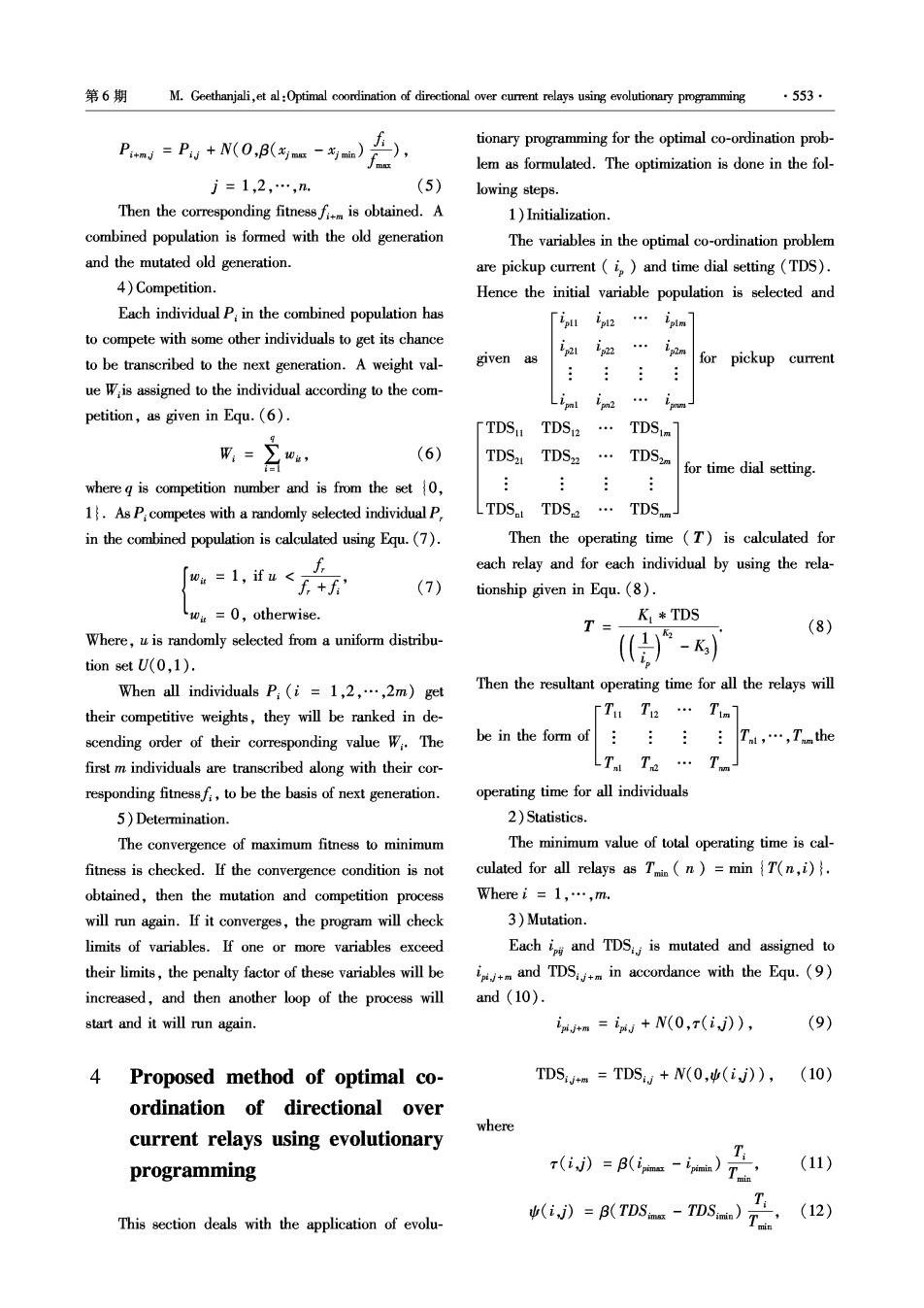
第6期 M.Geethanjali,et al:Optimal coordination of directional over current relays using evolutionary programming ·553· P+nd=Pu+N(0,B(m-i血) tionary programming for the optimal co-ordination prob- lem as formulated.The optimization is done in the fol- j=1,2,…,n. (5) lowing steps. Then the corresponding fitnessfm is obtained.A 1)Initialization. combined population is formed with the old generation The variables in the optimal co-ordination problem and the mutated old generation. are pickup current (i)and time dial setting (TDS). 4)Competition. Hence the initial variable population is selected and Each individual P:in the combined population has [ipl p2… iplm to compete with some other individuals to get its chance im to be transcribed to the next generation.A weight val- given as for pickup current ue Wis assigned to the individual according to the com- im2 petition,as given in Equ.(6). Lipl [TDSu TDS2 TDSim (6) 台 TDS2 TDS2 TDS2m for time dial setting. where g is competition number and is from the set0, 1.As P:competes with a randomly selected individual P LTDS TDS TDS. in the combined population is calculated using Equ.(7). Then the operating time (T)is calculated for 「a=1,ifw<E+f each relay and for each individual by using the rela- (7) tionship given in Equ.(8). w=0,otherwise. T= K TDS (8) Where,u is randomly selected from a uniform distribu- -K) tion set U(0,1). When all individuals P:(i=1,2,.,2m)get Then the resultant operating time for all the relays will their competitive weights,they will be ranked in de- T Te Tim scending order of their corresponding value Wi.The be in the form of Tni,…,Tthe first m individuals are transcribed along with their cor- Ta… responding fitnessf:,to be the basis of next generation. operating time for all individuals 5)Determination. 2)Statistics. The convergence of maximum fitness to minimum The minimum value of total operating time is cal- fitness is checked.If the convergence condition is not culated for all relays as Tin n)=min T(n,i). obtained,then the mutation and competition process Where i=l,…,m. will run again.If it converges,the program will check 3)Mutation. limits of variables.If one or more variables exceed Each ip and TDS is mutated and assigned to their limits,the penalty factor of these variables will be j+m and TDS+m in accordance with the Equ.(9) increased,and then another loop of the process will and (10). start and it will run again. tm=+N(0,r(i,j》), (9) 4 Proposed method of optimal co- TDS4m=TDS,+N(0,(i,J),(10) ordination of directional over where current relays using evolutionary programming r》=风ea)层 (11) (i》=B(TDss-TDSa)T点 (12) This section deals with the application of evolu-
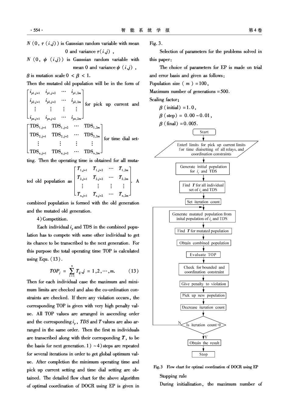
·554, 智能系统学报 第4卷 N(0,T (i,j))is Gaussian random variable with mean Fig.3. 0 and variancer(ij), Selection of parameters for the problems solved in N(0,(i,j))is Gaussian random variable with this paper: mean 0 and variance (i,j), The choice of parameters for EP is made on trial B is mutation scale 0 <B<1. and error basis and given as follows: Then the mutated old population will be in the form of Population size m )=100, 「ipljt ipjt2…pl,2n Maximum number of generations=500. ipjtl ipj2 i2,2m Scaling factor; for pick up current and B (initial)=1.0, Limjtl im*2… im.2m B(step)=0.00~0.01, [TDSi+ TDS1.+2 TDS1.m B(final)=0.005. TDS2.TDS2 TDS2.2m Start for time dial set- Enterl limits for pick up current limits LTDS.+ TDS.+2 TDS.2m- for time diaisetting of all relays,and coordination constraints ting.Then the operating time is obtained for all muta- [Ti T12 … T1.2m Generate initial population for i and TDS ted old population as T2*1 T2*2 …T2.2m A Find T for all individual set of i,and TDS LTnjtt TnN2… Tn2m combined population is formed with the old generation Set iteration count and the mutated old generation. Generate mutated population from 4)Competition. inital population of i,and TDS Each individual i,and TDS in the combined popu- Find T for mutated population lation has to compete with some other individual to get its chance to be transcribed to the next generation.For Obtain combined population this purpose the total operating time TOP is calculated Evaluate TOP using Equ.(13). Check for bounded and T0P=7W=1,2…,m (13) coordination constraint Then for each individual case the maximum and mini- Give penalty to violation mum limits are checked and also the co-ordination con- straints are checked.If there any violation occurs,the Pick up new population corresponding TOP is given with very high penalty val- Decrease iteration count ue.All TOP values are arranged in ascending order and the correspondingi,TDS and Tvalues are also ar- N Is iteration count-0 ranged in the same order.Then the first m individuals are transcribed along with their corresponding T,to be y the basis for next generation.1)~4)steps are repeated Obtain the result for several iterations in order to get global optimum val- Stop ue.After completion the minimum operating time and pick up current setting and time dial setting are ob- Fig.3 Flow chart for optimal coordination of DOCR using EP tained.The detailed flow chart for the above algorithm Stopping rule of optimal coordination of DOCR using EP is given in During initialization,the maximum number of
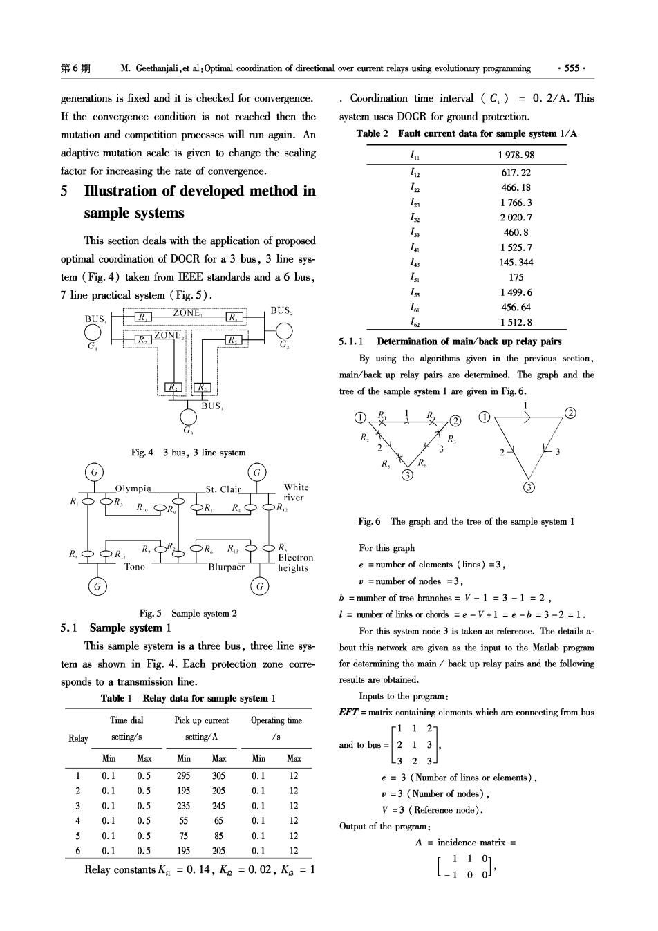
第6期 M.Geethanjali,et al:Optimal coordination of directional over current relays using evolutionary programming ·555· generations is fixed and it is checked for convergence. Coordination time interval (C:)=0.2/A.This If the convergence condition is not reached then the system uses DOCR for ground protection. mutation and competition processes will run again.An Table 2 Fault current data for sample system 1/A adaptive mutation scale is given to change the scaling 1978.98 factor for increasing the rate of convergence. In2 617.22 5 Illustration of developed method in Ia 466.18 13 1766.3 sample systems 1知 2020.7 L知 460.8 This section deals with the application of proposed I 1525.7 optimal coordination of DOCR for a 3 bus,3 line sys- 18 145.344 tem (Fig.4)taken from IEEE standards and a 6 bus, l 175 7 line practical system (Fig.5). Is 1499.6 BUS 16 456.64 BUS, R ZONE R 1512.8 G G 5.1.1 Determination of main/back up relay pairs By using the algorithms given in the previous section, main/back up relay pairs are determined.The graph and the tree of the sample system 1 are given in Fig.6. BUS ① ,② ① R R Fig.4 3 bus,3 line system 3 R R G G Olympia St.Clair White ③ RR,R宁R river 之R,R R Fig.6 The graph and the tree of the sample system 1 R, PR R,SR. 5R,R,子R For this graph ectron Tono Blurpaer heights e number of elements (lines)=3, G G v=number of nodes =3, b =number of tree branches=V-1 =3-1 =2. Fig.5 Sample system 2 I=number of links or chords =e-V+1 =e-b=3-2 =1. 5.1 Sample system 1 For this system node 3 is taken as reference.The details a- This sample system is a three bus,three line sys- bout this network are given as the input to the Matlab program tem as shown in Fig.4.Each protection zone corre- for determining the main back up relay pairs and the following sponds to a transmission line. results are obtained. Table 1 Relay data for sample system 1 Inputs to the program: EFT=matrix containing elements which are connecting from bus Time dial Pick up current Operating time r1127 Relay setting/s setting/A 18 and to bus =2 1 3, Min Max Min Max Min Max L323」 1 0.1 0.5 295 305 0.1 12 e =3(Number of lines or elements), 2 0.1 0.5 195 205 0.1 12 v=3 (Number of nodes), 3 0.1 0.5 235 245 0.1 12 V=3 (Reference node). 4 0.10.5 55 65 0.1 12 0.10.5 6 Output of the program: 85 0.1 12 A incidence matrix 60.1 0.5 195205 0.1 12 「1101 Relay constants Ki =0.14,K2 =0.02,K3 =1 L-100J
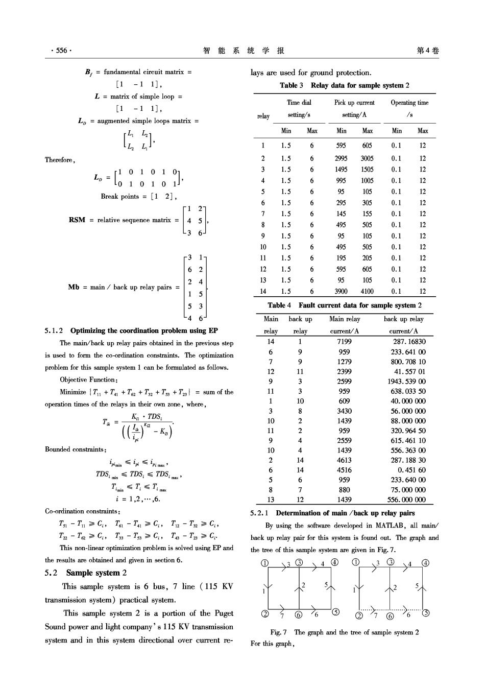
·556· 智能系统学报 第4卷 B.=fundamental circuit matrix lays are used for ground protection. [1-11], Table 3 Relay data for sample system 2 L=matrix of simple loop Time dial Pick up current Operating time [1-11], relay setting/s setting/A /8 Lp augmented simple loops matrix rL1L21 Min Max Min Max Min Max 五 1 1.5 6 595 605 0.1 12 Therefore, 1.5 6 2995 3005 0.1 白 -690901 1.5 6 1495 1505 0.1 12 4 1.5 6 995 1005 0.1 3 5 1.5 6 95 105 0.1 Break points =[1 2], 12 6 1.5 295 305 0.1 12 127 1.5 145 155 0.1 12 RSM relative sequence matrix 45, 1.5 6 495 505 0.1 3 L3 6J 9 1.5 6 95 105 0.1 2 10 1.5 6 495 505 0.1 12 3 17 11 1.5 6 195 205 0.1 12 6 2 12 1.5 6 595 605 0.1 12 2 4 13 1.5 6 95 105 0.1 12 Mb main back up relay pairs 1 5 141.5 6 3900 4100 0.1 12 5 3 Table 4 Fault current data for sample system 2 LA 6 Main back up Main relay back up relay 5.1.2 Optimizing the coordination problem using EP relayrelay current/A current/A The main/back up relay pairs obtained in the previous step 14 7199 287.16830 is used to form the co-ordination constraints.The optimization 6 9 959 233.64100 > 9 1279 800.70810 problem for this sample system 1 can be formulated as follows. 12 11 2399 41.55701 Objective Function: 9 3 2599 1943.53900 Minimize Tu+Ta +Ts2 +T32 +Tss +T=sum of the 1 3 959 638.03350 operation times of the relays in their own zone,where, 1 10 609 40.000000 8 3430 56.000000 T= K·TDS 10 2 1439 88.000000 -K) 11 2 959 320.96450 9 4 2559 615.46110 Bounded constraints: 10 1439 556.36300 in≤≤n好, 4613 287.18830 TDS:h≤TDS:≤TDS:r, 6 14 4516 0.45160 5 6 959 233.64000 Tn≤T,≤Tinm 8 7 880 75.000000 i=1,2,…,6. 13 12 1439 556.000000 Co-ordination constraints: 5.2.1 Determination of main /back up relay pairs T1-T1≥C,T61-T41≥C,T2-Tn≥C, By using the software developed in MATLAB,all main/ T2-Ta≥C,Ta-Ta≥C,T8-Tg≥C back up relay pair for this system is found out.The graph and This non-linear optimization problem is solved using EP and the tree of this sample system are given in Fig.7. the results are obtained and given in section 6. ① 3®4④03>40 5.2 Sample system 2 This sample system is 6 bus,7 line (115 KV 2不 transmission system)practical system. This sample system 2 is a portion of the Puget Sound power and light company's 115 KV transmission Fig.7 The graph and the tree of sample system 2 system and in this system directional over current re- For this graph

6M.Geethanjali,et al:Optimal coordination of directional over current relays using evolutionary programming ·557· e number of elements (lines)=7, r14 1 v=number of nodes =6, 6 b number of tree branches =v-1 =6-1 =5, 7 9 number of links or chords 12 11 e-w+1=e-b=7-5=2. 93 For this system,node 3 is taken as reference.The details 11 3 about the network are given as the input to the Matlab program 1 10 for determining the main/back up relay pairs,and the following 38 results are obtained. Mb =Main/back up relay pairs 102 Input to the program 112 Γ1127 9 4 263 10 4 313 14 EFT =44 3 6 554 5 6 665 7 L762 1312 e =7(numbers of lines or elements), Even though twenty main/back up relay pairs were available for v=6 (numbers of nodes), this system only seventeen pairs were considered for the sake of V=6 (reference nodes). simplification. Output of the program: 5.2.2 Optimizing the co-ordination A incidence matrix The main/back up relay pairs obtained in the previous sec- Γ1010000 tion is used to form the co-ordination constraints.The optimiza -100000-1 tion problem for this example system can be formulated as fol- 0-1-1-1000, lows. 0 0001-10 Objective function: 00001-1 0 MinimizeT +T2 +T3+T+Ts +Ts+T+Ts+To+ B=fundamental circuit Matrix Tio+Tn+Ti2+Ti Tul. 「0-1011101 Where, 1-1-110001 Ka TDS T:= Lp =matrix of simple loops Γ0-1011107 Bounded constraints: -1-100011, inna≤in:≤nnr L-101-1-1-11 TDS≤TDS,≤TDS. Lp augmented simple loops matrix Tinn≤T≤Tis Γ00011100100000 i=1,2,…,14. 00100011100000 Co-ordination constraints 00100 1100000 T1-T4≥C,T,-T6≥C,T,-T,≥C, 001000 11001110 T1-T2≥C,T3-T,≥C,T3-T1≥C, 01000000001110 To-T1≥C,Ts-T3≥C,T2-T0≥C, 10011100010001 T2-T≥C,T4-T,≥C,T4-T0≥C, 10011100010001 T4-T2≥C,T4-T6≥C,T6-T≥Ci, break points =[1 9 11], T,-Tw≥C,T2-T13≥C RSM relative sequence matrix This non-linear optimization problem is solved using EP and the Γ19107 results are obtained and given in Table 6. 31000 6 Results and analysis 8240 -146712- The simulated results for sample system 1 are giv-
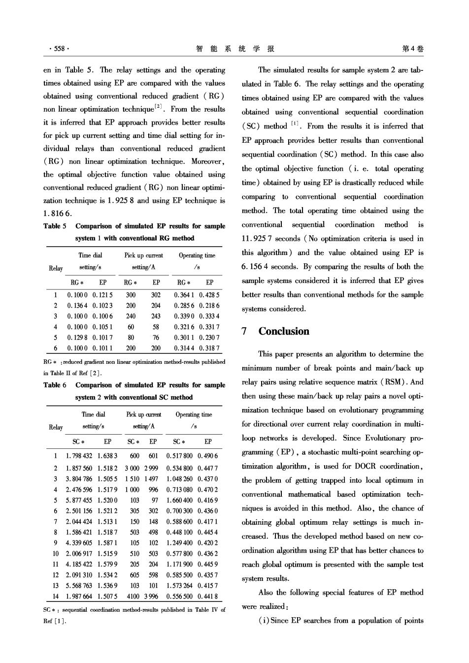
·558. 智能系统学报 第4卷 en in Table 5.The relay settings and the operating The simulated results for sample system 2 are tab- times obtained using EP are compared with the values ulated in Table 6.The relay settings and the operating obtained using conventional reduced gradient (RG) times obtained using EP are compared with the values non linear optimization technique2).From the results obtained using conventional sequential coordination it is inferred that EP approach provides better results (SC)method 1.From the results it is inferred that for pick up current setting and time dial setting for in- EP approach provides better results than conventional dividual relays than conventional reduced gradient sequential coordination (SC)method.In this case also (RG)non linear optimization technique.Moreover, the optimal objective function (i.e.total operating the optimal objective function value obtained using time)obtained by using EP is drastically reduced while conventional reduced gradient (RG)non linear optimi- zation technique is 1.925 8 and using EP technique is comparing to conventional sequential coordination 1.8166. method.The total operating time obtained using the Table 5 Comparison of simulated EP results for sample conventional sequential coordination method is system 1 with conventional RG method 11.925 7 seconds (No optimization criteria is used in Time dia Pick up current Operating time this algorithm)and the value obtained using EP is Relay setting/s setting/A 6.1564 seconds.By comparing the results of both the RG* 勿 RG* 多 RG* EP sample systems considered it is inferred that EP gives 10.10000.1215 300 302 0.36410.4285 better results than conventional methods for the sample 20.13640.1023 200 204 0.28560.2186 systems considered. 30.10000.1006 240 243 0.33900.3334 40.10000.1051 60 58 0.32160.3317 7 Conclusion 50.12980.1017 76 0.30110.2307 60.10000.1011 200 200 0.31440.3187 This paper presents an algorithm to determine the RG *reduced gradient non linear optimization method-results published minimum number of break points and main/back up in TableⅡof Ref[2] Table 6 Comparison of simulated EP results for sample relay pairs using relative sequence matrix(RSM).And system 2 with conventional SC method then using these main/back up relay pairs a novel opti- Time dial Pick up current Operating time mization technique based on evolutionary programming Relay setting/s setting/A /8 for directional over current relay coordination in multi- SC* EP SC* EP SC* EP loop networks is developed.Since Evolutionary pro- 11.7984321.6383 6006010.5178000.4906 gramming (EP),a stochastic multi-point searching op- 21.8575601.518230002999 0.5348000.4477 timization algorithm,is used for DOCR coordination, 33.8047861.5055151014971.0482600.4370 the problem of getting trapped into local optimum in 42.4765961.51791000996 0.7130800.4702 55.8774551.520010397 conventional mathematical based optimization tech- 1.6604000.4169 62.5011561.5212 305302 0.7003000.4360 niques is avoided in this method.Also,the chance of 72.0444241.5131 150148 0.5886000.4171 obtaining global optimum relay settings is much in- 81.5864211.5187 503 498 0.4481000.4454 creased.Thus the developed method based on new co- 94.3396051.5871105102 1.2494000.4202 102.0069171.51595105030.5778000.4362 ordination algorithm using EP that has better chances to 114.1854221.57992052041.1719000.4459 reach global optimum is presented with the sample test 122.0913101.53426055980.5855000.4357 system results. 135.5687631.53691031011.5732640.4157 141.9876641.5075410039960.5565000.4418 Also the following special features of EP method SC:sequential coordination method-results published in Table IV of were realized: Ref [1]. (i)Since EP searches from a population of points